Process Control ~ Learning Instrumentation And Control Engineering Learning Instrumentation And Control Engineering

Instrument Air System Design, Sizing and Distribution

Custom Search

 Design of Instrument Air System

Every plant requires instrument air system for some form of pneumatic control. The design of the design, sizing and distribution of instrument air is different from plant to plant depending on the location, the environment, and the number of instruments to be supplied instrument gas.

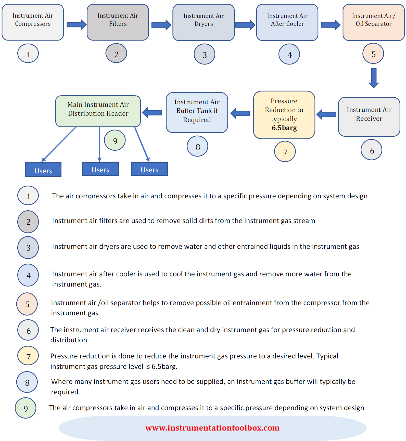
Below is illustrated a typical instrument air system design that you will find in a typical plant. Note that the blocks 1 to 5 illustrated in the schematic below are typically part of a vendor package. The vendor supplies these units as a package:

Sizing and Distribution

Normally, instruments in the unit requiring an air supply will be fed from carbon steel air headers or sub-headers.  Take-off valves in all Unit areas will be provided by piping on the instrument air main header. 

These take-off valves will be installed at each rack column. Connections to instrument air main headers will always be at the upper section of the pipe. Branch-off points for future extensions in an instrument main header will be provided with an isolating valve and plug. 

The sub-headers will be provided with drain valves at low point and at dead ends and are to be sized in accordance with the following table:

No. of Instrument Air Users

Nominal Diameter

1-6

1/2"

7-12

3/4"

13-25

1"

26-50

1 1/2"

51-100

2"


Instrument Ranges Used in Process Control System Design

Custom Search

In process control design process variables such as temperature, pressure, flow, level, valve signals, analyzers etc are ranged in such a manner to be proportional to the primary signal as much as possible for control purposes. The table below shows the typical instrument scales employed in process control system design:

Instrument Variable

Scale

Temperature

Direct Reading

Pressure

Direct Reading

Flow (differential)

0 – 100 linear

Flow (Linearized)

0 – 100 linear

Level

0 – 100 linear

Analyzer

Direct Reading

Signal to Valves

0 – 100%

As far as possible, the instrument ranges will be selected such that the normal value will be between 50 and 75% of the adjusted range taking into account the specified minimum and maximum values and trip settings will lie between 10% and 90% of the adjusted range.

Typical accuracy of the pressure and differential pressure Smart transmitters will be +/- 0.25% of the calibrated span.

Typical accuracy of temperature Smart transmitters will be +/- 0.3% of the calibrated span.

Typical accuracy of the other transmitters will be as far as possible better than +/- 0.5%.


Basics of Split-Range Control in Control Valve Applications

Custom Search

In many process control applications in industry, it is sometimes desirable to have multiple control valves respond to the output of a single common controller. Control valves configured in this way to follow the command of a single controller are said to be split-ranged, or sequenced.

Split-ranged control valves may assume different forms of sequencing. Common modes of control valve sequencing seen in the process industry are:  complementary, exclusive, and progressive.

Complementary Split-Range Control
With this form of split-ranging, there is never a condition in the controller’s output range where both valves are fully open or fully shut. Rather, each valve complements the other’s position.  A typical example of complementary split-range control is a situation where two valves serve to proportion a mixture of two fluid streams, such as where base and pigment liquids are mixed together to form colored paint as shown below:
Example of complementary split-range control.


Both base and pigment valves operate from the same controller output signal. While the pigment valve is Air-To-Open, the base valve is Air-To-Close. The following table shows the relationship between valve opening for each control valve and the controller’s output:
Controller Output (%)
I/P Output (PSI)
Pigment Valve (Stem position)
Base Valve (Stem position)
0
3
Fully Closed
Fully Open
25
6
25% Open
75% Open
50
9
Half-Open
Half - Open
75
12
75% Open
25% Open
100
15
Fully Open
Fully Closed

Exclusive Split-Range Control
The nature of valve sequencing in this type of split-range control is to have an “EITHER OR” throttled path for process fluid. That is, either process fluid flows through one valve or through the other, but never through both at the same time.

This type of split-ranged control valves call for a form of valve sequencing where both valves are fully closed at a 50% controller output signal, with one valve opening fully as the controller output drives toward 100% and the other valve opening fully as the controller output goes to 0%.

A practical example of this form of split-ranging is in reagent feed to a pH neutralization process, where the pH value of process liquid is brought closer to neutral by the addition of either acid or caustic:
Exclusive Split-Range Control

The basic operating principle of the above process is:
  1. A pH analyzer monitors the pH value of the mixture and a single pH controller commands two           reagent valves to open when needed.

  2. If the process pH begins to increase, the controller output signal increases as well (direct action)         to open up the acid valve.

  3. The addition of acid to the mixture will have the effect of lowering the mixture’s pH value.

  4. Conversely, if the process pH begins to decrease, the controller output signal will decrease as      well, closing the acid valve and opening the caustic valve.

  5. The addition of caustic to the mixture will have the effect of raising the mixture’s pH value.
The Air-To-Open acid valve has an operating range of 9 to 15 PSI, while the Air-To-Close caustic valve has an operating of 9 to 3 PSI. The table below shows the relationship between valve opening for each control valve and the controller’s output:

Controller Output (%)
I/P Output (PSI)
Acid Valve (Stem position)
Caustic Valve (Stem position)
0
3
Fully Closed
Fully Open
25
6
Fully Closed
Half - Open
50
9
Fully Closed
Fully Closed
75
12
Half - Open
Fully Closed
100
15
Fully Open
Fully Closed

Progressive Split-Range Control
This form of split-range control for control valves is used to expand the operating range of flow control for some fluid beyond that which a single control valve could deliver. In this type of control, one of the valve usually a small valve opens gradually and becomes fully open at 50% of controller output while the large valve will remain shut at until the controller output goes beyond 50% when it starts opening. Both valves become fully open when controller output is 100%.

An example of progressive split-range control is a pH control process where the incoming liquid always has a high pH value, and must be neutralized with acid as shown below:
An example of progressive split-range control

The PH of the incoming water to be treated is measured by the analyzer, AT. As the output of controller AIC increases, the small acid valve starts to open and becomes fully open at 50% of controller output. Meanwhile the large acid valve will remain shut until controller output goes beyond 50%. At 100%, both small and large acid valves are fully open to ensure that the PH of the incoming water is neutralized.

Controller output and valve status for proper sequencing of the small and large acid control valves is shown below:

Controller Output (%)
I/P Output (PSI)
Small Acid Valve (Stem position)
Large Acid Valve (Stem position)
0
3
Fully Closed
Fully Closed
25
6
Half Open
Fully Closed
50
9
Fully Open
Fully Closed
75
12
Fully Open
Half Open
100
15
Fully Open
Fully Open


The Basics of PID Control

Custom Search

Having been introduced to the basic principles of feedback control modes, we now discuss how these modes can be applied to real life control problems.
It should now be clear that using proportional, integral or derivative mode alone cannot achieve the desired control objective. What works is a combination of these modes. 
By using all the three control modes together, we can:
(1) Hold the process near set point without major fluctuations with proportional       control.
(2) Eliminate offset with integral control.
(3) Achieve rapid response to major disturbances with derivative control.

PID Relationships:
(1) P-Control is the principle method of control and should do most of the work
(2) I-Control is added carefully just to remove the offset left behind by P-control.
(3) D-Control is there for stability only. It should be set up so that its stabilizing effect is larger than the destabilizing effect of I-control. D-Control is never used in a system that has a lot of noise.
Below is shown a feedback control system having a PID Controller


Feedback Control Modes: Proportional, Integral, Derivative

Custom Search

Feedback control is the most popular control system in use today in industrial control systems. The basic function of feedback control is to compute the error as the difference between the controlled variable and the set point; calculate and then output the signal to a control valve actuator based on the error.

To perform this function, feedback control can be operated in three modes:
(a) Proportional or Gain Mode
(b) The Integral or Reset Mode
(c) The Derivative or Rate Mode

Here we shall discuss the basic function and aspects of the Proportional, Integral and the Derivative modes of feedback control systems.

The Proportional Mode:
The purpose of the proportional mode is to cause an instantaneous response in the
controller output to changes in the error. The formula for the proportional mode is given by:


Process Control Basics: Cascade Control

Custom Search

In a cascade control system, two or more controllers are cascaded to control one or more process variable. Controllers are said to be "in cascade" when the output (OP.1) of the first or primary controller (master) is used to manipulate the set-point(SP.2) of another or secondary controller (slave). When two or more controllers are cascaded, each will have its own measurement input (PV.1, PV.2) but only the primary controller can have an independent set-point (SP.1) and only the secondary controller has an output (OP.2) to the process. This concept of cascade control is illustrated in the diagram below:
Block Diagram of a Cascade Control System


Process Control Basics: Feedforward and Closed Loop Control

Custom Search

Feedforward Control
Feedforward control is a control system that anticipates load disturbances and controls them before they can impact the process variable (PV). It is a form of open loop control, as the process variable is not used in the control action. In feedforward control the major process variables(A1, A2 & A3) are fed into a model to calculate the manipulated variable (MV) required to control at setpoint (SP). For feedforward control to work effectively, the user must have a mathematical understanding of how the manipulated variable(s) will impact the process variable(s)


Process Control Basics

Custom Search

What is a Process?
The word ‘Process’ used popularly in process control and the process industry refers to the ways and methods applied in changing or refining raw materials into end products suitable for mankind. The raw materials which can either be in a liquid, gaseous or a mixture of solid and liquid(slurry) are during processing transferred, measured, mixed, heated or cooled, filtered, stored, or handled in some other way to produce the end product.
Process industries include the chemical industry, the oil and gas industry, the food and beverage industry, the pharmaceutical industry, the water treatment industry, and the power industry.

What is Process Control?
Process Control refers to the methods used to control process variables during the manufacture


How a Process Control Loop Works in Automatic Control Systems

Custom Search

In today’s modern plants, processes are controlled to achieve desired objectives. The term control means methods or means used to force parameters in the environment to have specific or desired values. To achieve control, several elements are coordinated together to achieve the control objective. All the elements necessary to accomplish the control objectives, including the instrumentation systems, are usually described by the term control system.

Control can either be manual or automatic. Manual control involves human intervention and it often entails forcing a given parameter to specific value with the human factor actually carrying out the control function. For example, suppose we want to control the level of water in an open tank which has an inlet valve through which water passes, all we simply do is to station an operator who basically uses his judgement to close the valve when the tank has become full or open the valve when the tank is almost empty.

In automatic control, no human intervention is required rather sensors, controllers, actuators and other control elements are used to automatically control a system to force the system parameters to desired levels.


You May Also Like: