Pneumatic Systems ~ Learning Instrumentation And Control Engineering Learning Instrumentation And Control Engineering

How to Calibrate a Fisher 3582 Pneumatic Valve Positioner

Custom Search


The valve positioner is a critical component in the control valve loop as it helps to accurately position the valve during the control process. However, failure to calibrate the positioner accurately could lead to wrong valve positioning which could in turn have significant impact on the process where the control valve is being used. Imagine supplying a customer natural gas at 5barg through a control valve controlled by a controller taking signal from the supply to the customer. If pressure suddenly goes to 7barg and the controller gives a signal to the control valve to close more to bring the pressure to 5barg, if the control valve is wrongly positioned and fails to close more, we could be giving the customer more than 5barg! This could be catastrophic and lead to undesirable consequences.

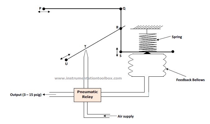
In view of the importance of a positioner in accurately positioning the control valve plug, the need to accurately calibrate the valve positioner cannot be over emphasized. The set up below illustrates the basic components required to calibrate a control valve positioner:


Before studying this procedure, read : How a Pneumatic Valve Positioner Works 

Procedure for Calibrating a Pneumatic Valve Positioner

Step 1
Shut off the supply pressure to the valve positioner. Connect or reconnect the necessary tubing from the valve positioner output to the actuator supply connection. Connect the input to the valve positioner and set the input signal value at mid-range.

Step 2
Move the flapper assembly to approximately position 6 in the proper operating quadrant of the beam (direct or reverse acting), and apply supply pressure to the valve positioner. The 0 degree index marks on the rotary shaft arm should align with the case index marks as shown in diagram below and the actuator should be at its mid-travel position. If not, first check for loose linkage or improper cam installation. A minor nozzle height adjustment might be necessary to make the desired input signal value correspond to the starting point of travel.
Positioner Beam and Arm Index Marks. Photo Credit: Fisher

Step 3
Apply an input signal equal to the low value of the input signal range. If your positioner is a 0.2bar – 1.2 bar range (3 to 15psig) input range, set the input to 3psig. Loosen the nozzle locknut and adjust the nozzle until the actuator moves to the proper end of its travel. Changing the nozzle position is intended only as a means of zero trim adjustment. Whenever nozzle position is changed, the zero reference point is changed. 

Step 4
Apply an input signal equal to the high value of the input signal range (15psig, if using a 3 to 15psig positioner) and observe the actuator stem travel. If the stem travel is short of its expected range, increase the travel by moving the flapper assembly to a higher number on the beam. If the desired stem travel occurs before the input signal reaches the high value of the input signal range, decrease the travel by moving the flapper assembly toward a lower number on the beam.

Step 5
Repeat steps 3 and 4 until the correct travel is achieved. Each time the flapper assembly position is changed in step 4, repeat step 3 to provide proper zero. Note that Moving the flapper assembly toward zero on the beam scale decreases stem travel.


How An Air Pressure Regulator Works

Custom Search

In pneumatic instrumentation systems, instrument air is required to power valve actuators and other instruments - transmitters, controllers, control valves etc. A key component of the instrument air supply system is an air pressure regulator. The air pressure regulator is a simple device.  It is used to lower the main instrument air supply of a plant to a pressure suitable for an air-operated instruments; eg, a transmitter, control valve, etc.  

Normally, each air operated instrument has its own regulator.  So an air regulator is one of the most common devices in the plant.  There are various manufacturers of air regulators, eg Masoneilan and Fisher.  However, they all work in much the same way.  The schematic of a Fisher air pressure regulator is shown below:


Principle of Operation of the Air Pressure Regulator
  1. The main air supply is connected to the AIR INLET PORT.  Air passes into  the filtering chamber at the bottom of the regulator.
  2. Air passes through the filter which removes dirt particles in the incoming air which may block nozzles etc.  It then goes into the valve assembly.
  3. The valve assembly is moved by the range spring pressing on the diaphragm.
  4. The range spring will hold the valve assembly down until the output pressure is high enough to lift the diaphragm (via the air passage shown).  At this point the small spring in the valve assembly closes the valve.
  5. Air is allowed to pass through a hole at the center of the diaphragm and out of the vent.  This maintains balanced pressure across the diaphragm.
  6. If the outlet pressure is above the pressure set by the range spring, the air will go out through the vent above the diaphragm.  When the outlet pressure is correct, the valve assembly opens to set the correct pressure. This pressure exits the regulator through the OUTLET AIR PORT
  7. If the outlet pressure is below the pressure set by the range spring the valve assembly will stay open until the set pressure is reached.


How the Foxboro 43AP Pneumatic Controller Works

Custom Search

The Foxboro 43AP pneumatic controller is a versatile process instrument controller that can be used to control pressure, temperature , flow and level. As with all process controllers, the Foxboro 43AP pneumatic controller continuously detects the difference between a process measurement and its set point, and produces an output air signal that is a function of this difference and the type of control. 
Controller Loop for a Pneumatic Controller
The output signal is transmitted to a control valve or other control device. The process measurement, set point, and output signal are indicated on the controller.

Foxboro Pneumatic Controller with Proportional, Reset and Derivative Actions and Automatic Manual Transfer System. Photo Credit: Foxboro
Principe of Operation of the 43AP Pneumatic Controller
The above schematic shows the basic internal parts of the mechanism of operation of a Foxboro 43AP pneumatic controller. The principle of operation of the device is explained below:

  1. A differential linkage measures difference between measurement pointer and setting index         positions as shown in the schematic above. This error signal moves proportioning lever.
  2. The proportioning lever pivots at its center on the end of a flat spring.
  3. This motion of the proportioning lever changes flapper nozzle relationship, causing relay to        establish an output pressure.
  4. This output pressure is fed back to the proportioning bellows, which acts through the                  proportioning lever to re-balance flapper nozzle.
As shown above, this particular controller model has reset bellows as well as a derivative tank. The reset bellows and tank assembly are used when measurement must be maintained exactly at control point -that is without “offset”. The derivative tank assembly is used to improve system response to a slow process.


Common Symbols Used in Pneumatic Systems and Instrumentations

Custom Search

Pneumatic Systems are still popular in older plants and even in modern plants where their use is inevitable. Pneumatic diagrams representing pneumatic systems have defined ways they are represented. They are commonly represented with symbols. These symbols needs to be understood before you can correctly interpret pneumatic drawings and diagrams. These common symbols are shown below:

Pneumatic Directional Control Valves Symbols
Symbols of Directional Control Valves (Photo Credit: AutomationDirect.com)


Symbols of Simple Pneumatic Valves
Pneumatic Valve Symbols (Photo Credit: AutomationDirect.com)


Line Symbols Used in Pneumatic Drawings
Line Symbols in Pneumatic Symbols (Photo Credit: AutomationDirect.com)


Symbols of Common Equipment Used in Pneumatic Drawings and Systems
Symbols of Common Pneumatic Equipment. (Photo Credit: AutomationDirect.com)

Common Actuator Symbols Used in Pneumatic Drawings
Actuator Symbols (Photo Credit: AutomationDirect.com)


Troubleshooting Guide for Pneumatic Field Transmitters

Custom Search

Pneumatic instruments are still a critical component in most instrumentation systems of today even though recent technology is making them to become somewhat obsolete. For plants where pneumatic instruments especially pressure transmitters are still being used, there are common problems with these instruments that are encountered in their everyday use. These problems are highlighted below so that when troubleshooting any potential problem with such instruments, we know what the culprits are.
Pressure Transmitter  Problem Possible Cause(s)
No Output
  • Bent flapper
  • No air supply; plugged restrictor (this is  very common)
  • Corroded pneumatic relay or components
  • Dirty pneumatic relay seats
  • Flapper is away from the nozzle due to freezing, improper adjustment, bent "C" flexure or transmitter has been dropped
  • Leak in the feedback bellows
  • Leak in the nozzle circuit
  • Leak in the sensor pressure circuit
  • Disconnected or broken links in a motion balance pressure transmitter
Partial Output
  • Plugged low pressure leg on a DP cell
  • Worn pneumatic relay parts
  • Partially plugged supply screen or filter
  • Burr on the flapper assembly
  • Hole in the flapper assembly
  • Damaged feedback bellows
  • Worn capsule diaphragms
  • Warped or distorted "C" or "A" flexure on a DP cell
  • Wrong range-sensing unit
  • Pin hole leaks in the control relay diaphragm
Full Output
  • Plugged nozzle
  • Ballooned capsule diaphragm
  • Loose nozzle lock nut
  • Blocked pneumatic relay vent
  • Sensing capsule impacted with process solids
  • Flapper assembly distorted or bent
Zero shift diaphragms
  • Dirty flapper assembly set point capsule problems - coating, fatigue, warped
  • Temperature changes -  either ambient or process temperatures
  • Process static pressure changes.
  • Worn zero or span adjustments
  • Flapper is depressed or hollowed on the surface
  • Pin hole leak in the flapper
  • Flashing and/or condensate on either leg of a DP cell installation
Output Oscillates
  • Liquid in the feedback bellows - water, oil etc
  • "C" flexure look nut loose
  • Close coupled pneumatic system
  • Loss of capsule fill fluid
  • Hole in the feedback bellows
  • Loose bleed/vent valves
  • Flashing due to pressure variations

The list of pneumatic field transmitters problem and their probable cause in the table above is by no means exhaustive. It is however a useful troubleshooting guide for pneumatic transmitters.

Read Also: Troubleshooting Guide for DP Transmitters


How a Pneumatic Pressure Transmitter Works

Custom Search

The Foxboro 11GM pneumatic pressure transmitter is a force-balance instrument used to measure pressure and transmits it as a proportional 3 – 15psig signal.
Pneumatic Pressure Transmitter. (Photo Credit: Foxboro)

As shown in the diagram of the transmitter, the pressure being measured is applied to a bellows capsule. The force on the capsule is transmitted through a flexure to the lower end of the force bar. The metal diaphragm seal serves as both a fulcrum for the force bar and as a seal for the pressure chamber. The force is transmitted through the flexure connector to the range bar which pivots on the range wheel.


Any movement of the range bar causes a minute change in the clearance between the flapper and the nozzle. This produces a change in the output pressure from the pneumatic relay to the feedback bellows until the force on the feedback bellows balances the force on the bellows capsule.

The output pressure established by this force-balance mechanism is the transmitted signal and is proportional to the pressure applied to the bellows capsule. This signal can be transmitted to a pneumatic receiver or controller for recording/indication or control purposes.


How a Pneumatic Valve Positioner Works

Custom Search

The pneumatic valve positioner accepts an input pneumatic signal from a control device and sends an increased or decreased output signal to a control valve to ensure the control valve plug travels correctly and is positioned properly on the valve seat. The schematic below illustrates how the valve positioner is connected to the control valve:

A valve positioner can be set to either direct-acting or reverse-acting. A direct-acting valve positioner sends an increased output signal to the control valve as the input signal to it increases. A reverse-acting valve positioner, sends a decreased output signal as the input signal to it increases.

How the Pneumatic Valve Positioner Works
The schematic below is that of a direct-acting Fisher 3582G pneumatic valve positioner:
Fisher 3582G Pneumatic Valve Positioner (Photo Credit : Fisher)

As shown in the diagram, the valve positioner is attached to a diaphragm-actuated sliding stem control valve. The supply pressure is connected to a pneumatic relay. A fixed orifice restriction in the relay limits flow to the nozzle such that when the flapper is not restricting the nozzle, air can bleed out faster than is being supplied.

The input signal from the control device is connected to the bellows. When the input signal increases, the bellows expand and moves the beam. The beam pivots about the input axis moving the flapper closer to the nozzle. The nozzle pressure increases and through the pneumatic relay action increases the output pressure to the valve actuator. The increased output pressure to the actuator causes the actuator stem to move downward. Stem movement is then fed back to the beam by means of a cam. As the cam rotates, the beam pivots about the feedback axis to move the flapper slightly away from the nozzle. The nozzle pressure decreases and reduces the output pressure to the actuator. Stem movement continues backing the flapper away from the nozzle until equilibrium is achieved.

When the input pressure decreases, the bellows contracts (aided by an internal range spring) and the beam pivots about the input axis to move the flapper away from the nozzle. Nozzle pressure decreases and the pneumatic relay permits the release of diaphragm casing pressure to atmosphere causing the actuator stem to move upward. Through the cam, stem movement is fed back to the beam to re-position the flapper closer to the nozzle. When equilibrium conditions are attained, stem movement stops and the flapper is positioned to prevent any further decrease in diaphragm case pressure.

In a reverse-acting valve positioner, the same basic operating principle above applies except that as the input signal increases, the diaphragm casing pressure is decreased. A decreasing input signal causes an increase in pressure to the diaphragm casing of the control valve.

How to Change Valve Positioner Action of the 3582G Pneumatic Valve Positioner
Positioner Beam (Photo Credit: Fisher)

The position of the flapper assembly on the beam determines whether the valve positioner will act as direct-acting or reverse-acting.  

As shown in the diagram above, the  beam is divided into quadrants. The direct acting quadrant is labelled DIRECT and the reverse-acting quadrant is labelled REVERSE. To change the valve positioner action, simply move the flapper assembly to the opposite quadrant of the beam.


How The Motion-Balance System used in Pneumatic Instruments Works

Custom Search

The motion - balance system is used in pneumatic instruments to produce a proportional output of 3 - 15 psig when a corresponding input signal is applied to the instrument. A typical motion-balance system in a pneumatic instrument is shown below:

The above diagram shows a motion-balance system in which the input motion is applied to point P on the lever PQ. The opposite end (Q) of this lever is pivoted to a second lever QRS which in turn has point S pivoted in a lever positioned by movement of the feedback bellows. 


At the center (R) of the lever QS there is a stem on which one end of the lever RTU is supported while it is pivoted at point U and has a flapper nozzle sensor located at point T. A horizontal displacement which causes P to move to the left is transmitted via Q to R, and as a result the flapper at T moves off the nozzle so that the back pressure falls. This change is amplified by the pneumatic relay so that the pressure in the feedback bellows falls and the lever carrying the pivot S moves down until equilibrium is re-established. The output pressure is then proportional to the original displacement. By changing the inclination of the lever RTU sensitivity or gain of the system may be changed.

The motion-balance principle has been applied successfully in pneumatic temperature measuring devices while the force-balance principle is common pneumatic differential pressure transmitters, pressure, flow and level instruments.


Pneumatic Instrumentation Principles – The Force Balance System

Custom Search

Virtually all pneumatic instruments used for measuring process parameters such as pressure, flow, level and temperature use a flapper/nozzle sensor and pneumatic relay . In real pneumatic instruments, there are two basic schemes for utilizing the flapper/nozzle/pneumatic relay system, namely, the motion-balance and the force-balance systems.
Force - balance principle in pneumatic systems
As shown above, when an input pressure signal, is applied to a bellows which is opposed by a similar bellows for the reference signal, the differential force applied to the lever supported on an adjustable pivot is opposed by a spring/bellows combination. Adjacent to the bellows is a flapper/ nozzle sensor. 

During operation, if the input signal exceeds the reference signal, the resultant force causes the force bar to rotate clockwise about the adjustable pivot so that the flapper moves closer to the nozzle, with the result that the pressure in the output bellows increases until  equilibrium of the force bar is re-established. The change in output pressure is then proportional to the change in the measurement signal and a standard 3 – 15 psig signal is generated.

Practically all pneumatic measuring systems depend on a primary element such as an orifice plate, Bourdon tube, etc., to convert the physical parameter to be measured into either a force or a displacement which, in turn, can be sensed by some form of flapper/nozzle sensor or used directly to operate a mechanism such as an indicator, a recorder pen, or a switch. The measurements most widely used in the process industries are temperature, pressure, flow, level, and density


Basics of Flapper Nozzle System and Pneumatic Relays Used in Pneumatic Instrumentation

Custom Search

Pneumatic systems are characterized by the simplicity of the technology on which they are based and the relative ease with which they can be installed, operated, and maintained. They are based on the use of a flapper and nozzle system in conjunction with a pneumatic relay (essentially a pneumatic amplifier) to detect a very small relative movement typically less than 0.01 mm and to control a supply of compressed air so that a considerable force can be generated under precise control.

How a Flapper Nozzle System Works in Pneumatic Instruments
A typical flapper/nozzle system is shown below. 

With the nozzle covered by the flapper, the pressure approaches the supply pressure, but when the flapper moves away from the nozzle the pressure falls rapidly to a value determined by the relative values of the discharge characteristics of the nozzle and the Orifice (restrictor). This variation in the back pressure P shown in the figure above with the flapper/ nozzle movement is shown below:
Variation of Nozzle back pressure with Flapper movement

This flapper nozzle system is the main stay of most pneumatic instruments. In a typical pneumatic instrument, the back pressure developed by the flapper nozzle movement is used to measure process pressure and other parameters in pneumatic instruments. A typical way to achieve this in pneumatic instrumentation is shown below.


How a 3 - 15psig Signal is generated in Pneumatic Instruments
How a 3 - 15psig is generated in pneumatic instruments
With process pressure sensed at the input bellows which causes the flapper to cover the nozzle and increase the back pressure P with increasing process pressure. A range and bias spring (S) is used to limit the bellows travel and establish reference conditions of output and input process. In this way, 3 - 15psig output signal proportional to the process input signal is generated. This is just a variant to illustrate how a 3 - 15psig is generated in pneumatic instruments. There are other sophisticated systems used but the underlying principle remains the same.

How a Pneumatic Relay Works
For measurement purposes the back pressure generated by the flapper nozzle system is usually amplified, and this is effected by means of a pneumatic relay.
Foxboro Type of Pneumatic Relay 

As shown above, the pneumatic relay comprises two chambers separated from each other by a flexible diaphragm that has a conical seat and a stem that act as a valve to cover or uncover the exhaust port. The stem acts against a small ball retained by the leaf spring so that it functions as a second valve which controls the flow of air from the supply to the output port.

During operation when the nozzle is covered, the pressure in the associated chamber builds up, causing the conical valve to close the exhaust port and the ball valve to allow air to flow from the supply to the output port so that the output pressure rises. When the nozzle is uncovered by movement of the flapper the flexible diaphragm moves so that the ball valve restricts the flow of air from the supply. At the same time the conical valve moves off its seat, opening the exhaust so that the output pressure falls. In this way, the output pressure is driven from 20 3 to 15 pig  (20KPa to 100KPa) as a result of the relative movement between the flapper and nozzle system


You May Also Like: