Flow meters ~ Learning Instrumentation And Control Engineering Learning Instrumentation And Control Engineering

Operating Principle of Variable Area Flow Meters

Custom Search

The variable area flowmeter is a reverse differential pressure meter used to accurately measure the flow rate of liquids and gases. The flow meter generally comprises a vertical, tapered glass tube and a weighted float whose diameter is approximately the same as the tube base.

How the Variable Area Flow Meter Works
The schematic below shows the basic design of a variable area flow meter:
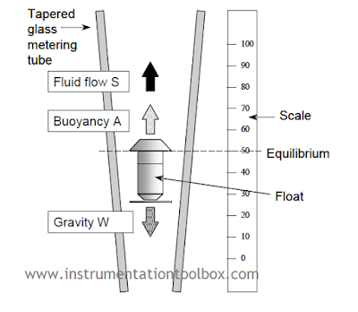
Basic Design of a Variable Area Flow Meter : Photo Credit Brooks Instrument
During operation, the fluid or gas flows through the inverted conical tube from the bottom to the top, carrying the float upwards as indicated by the arrow in our schematic above. Since the diameter of the tube increases in the upward direction, the float rises to a point where the upward force on the float created by differential pressure across the annular gap, between the float and the tube, equals the weight of the float.

As shown in the schematic above, three forces are seen acting on the float:

(a) A constant gravitational force, W.

(b) A buoyancy force, A, which is constant if the fluid density is constant (According to Archimedes principle)

(c) Flow resistance force S, the upward force of the fluid flowing past the float.

Two of these forces are acting in an upward direction as indicated by the arrows in the schematic above. They are the buoyancy force A and the flow resistance force S. The gravitational force W, acts downward.

When the float is stationary, W and A are constant and S must also be constant. In a position of equilibrium (floating state) the sum of forces S + A is opposite and equal to W and the float position corresponds to a flow rate that can be read off a scale. 

A major advantage of the variable area flowmeter is that the flow rate is directly proportional to the orifice area that, in turn, can be made to be linearly proportional to the vertical displacement of the float. Thus, unlike most differential pressure systems, it is unnecessary to carry out square root extraction.

Flow Rate Equation for the Variable Area Flow Meter
In a typical variable area flow meter, the flow Q can be shown to be approximately given by:
                 
$Q = CA\sqrt{ρ}$

where:
Q = flow
C = constant that depends mainly on the float
A = cross-sectional area available for fluid flow past the float
ρ = density of the fluid
As shown by the flow equation above, indicated flow depends on the density of the fluid which, in the case of gases, varies strongly with the temperature, pressure and composition of the gas.

Floats Used in Variable Area Flow Meters
A wide variety of float shapes are available for use in variable area flow meters. The weight, shape and materials of these floats are adapted to the individual installations. The common floats used are:
A. Ball float
B. Viscosity-immune float
C. Viscosity-dependent float
D. Float for low pressure drop


Different Shapes of Floats used for Variable Area Flow Meters. Photo Credit: ABB Flow

The ball float (A) is mainly used as a metering element for small flowmeters. The viscosity-immune float (B) is used in applications where viscosity change is a critical factor. The viscosity-dependent (C) float is used in larger sized variable area flowmeters. Floats for low pressure drop (D) applications are very light in weight with relatively low pressure drops. Its design requires minimum upstream pressures and is usually preferred for gas flow measurement.

Flow Metering Tubes
The meter tube of a variable area meter is normally manufactured from borosilicate glass that is suitable for metering process medium temperatures up to 200 °C and pressures up to about 2 - 3 MPa. Because the glass tube is vulnerable to damage from thermal shocks and pressure hammering, it is often necessary to provide a protective shield around the tube.

Variable area meters are inherently self-cleaning since the fluid flow between the tube wall and the float provides a scouring action that discourages the build-up of foreign matter. Nonetheless, if the fluid is dirty, the tube can become coated – affecting calibration and preventing the scale from being read. This effect can be minimised through the use of an inline filter.

The temperature and pressure range may be considerably extended (for example up to 400 °C and 70 MPa) through the use of a stainless steel metering tube. Again, the float can incorporate a built-in permanent magnet that is coupled to an external field sensor that provides a flow reading on a meter.

Floats Centering Methods in Variable Area Meters
An important requirement for accurate metering is that the float is exactly centered in the metering tube. One of three methods is usually used:

(a) Slots in the float head cause the float to rotate and center itself and prevent it sticking to the walls of the tube. Slots cannot be applied to all float shapes and, further, can cause the indicated flow to become slightly viscosity dependent.


(b) Three molded ribs within the metering tube cone, parallel to the tube axis, guide the float and keep it centered. This principle allows a variety of float shapes to be used and the metering edge remains visible even when metering opaque fluids.


(c) A fixed center guide rod within the metering tube is used to guide the float and keep it centered. The use of guide rods is confined mainly to applications where the fluid stream is subject to pulsations likely to cause the float to ‘chatter’ and possibly, in extreme cases, break the tube. It is also used extensively in metal metering tubes.

Floats Centering Methods in Variable Area Flow Meter Design

Materials Used in Construction of Floats
The float material is largely determined by the medium and the flow range and includes: stainless steel, titanium, aluminium, black glass, synthetic sapphire, polypropylene, Teflon, PVC, hard rubber, Monel, nickel and Hastelloy C.

Advantages of Using a Variable Area Flow Meter
1. It has wide range of applications.
2. It has a linear float response to flow rate change.
3. It has a 10 to 1 flow range or tum-down rate.
4. Easy sizing or conversion from one particular service to another.
5. Ease of installation and maintenance.
6. Simplicity and low cost.
7. High low-flow accuracy (down to 5 cm3/ min). 
8. Easy visualisation of flow

Disadvantages of Using a Variable Area Flow Meter
1. It has limited accuracy.
2. It is susceptibility to changes in temperature, density and viscosity.
3. Fluid medium must be clean, no solids content.
4. Erosion of device (wear and tear).
5. It can be expensive for large diameters application.
6. It operates in vertical position only.
7. It requires accessories for data transmission.



How a Coriolis Mass Flow Meter Works

Custom Search

The vast majority of flow meters in use today are volumetric. However, there are a few other applications where what is required is a mass flow meter. One of such mass flow meters is the Coriolis Mass Flowmeter that can measure both the mass of liquids and gases.

Today, commercial Coriolis flowmeters are gradually gaining prominence in flow measurement applications. Steady technical improvements on these meters since they first came into the markets in the 1970s have greatly increased their accuracy and acceptance in the process industries. Currently in the process industries, direct mass flow measurements represent a substantial and fast-growing percentage of worldwide flowmeter applications (15 to 20%). The diagram below shows the construction a U-shaped Coriolis mass flow meter:
Construction a Commercial Coriolis Mass Flow Meter. Photo Credit: Micro Motion


How a Coriolis Mass Flow Meter Works
A Coriolis flowmeter requires a force acting on a tube carrying a flowing fluid. This force deforms tubes through which the fluid flows. The amount of deformation depends directly on the mass flow rate through the tubes. Signals from sensors measuring this deformation provide a direct indication of the mass flowrate.
In a Coriolis meter measuring process mass flow rates, the flowmeter must rotate the fluid. In practice they rotationally oscillate the fluid, which produces equivalent Coriolis forces. Tube designs are U-shaped, S-shaped, or straight. 

Design and Working Principle of a Commercial Coriolis Meter
Inside U-shaped sensor housing, the U-shaped flow tube is vibrated at its natural frequency by a magnetic device located at the bend of the tube. The vibration is like that of a tuning fork, covering less than 0.1 in. and completing a full cycle about 80 times/sec. As the liquid flows through the tube, it is forced to take on the vertical movement of the tube as shown in the diagram below. When the tube is moving upward during half of its cycle, the liquid flowing into the meter resists being forced up by pushing down on the tube.
Operating Principle of the Coriolis Mass Flow Meter. Photo Credit : Micro Motion

Having been forced upward, the liquid flowing out of the meter resists having its vertical motion decreased by pushing up on the tube. This action causes the tube to twist. When the tube is moving downward during the second half of its vibration cycle, it twists in the opposite direction.

Having been forced upward, the liquid flowing out of the meter resists having its vertical motion decreased by pushing up on the tube. This action causes the tube to twist. When the tube is moving downward during the second half of its vibration cycle, it twists in the opposite direction. The amount of twist is directly proportional to the mass flow rate of the liquid flowing through the tube. Magnetic sensors located on each side of the flow tube measure the tube velocities, which change as the tube twists. The sensors feed this information to the electronics unit, where it is processed and converted to a voltage proportional to mass flow rate. The meter has a wide range of applications from adhesives and coatings to liquid nitrogen.

Commercial Coriolis flowmeters design incorporate identical dual tubes oscillating in opposite directions. The flow from process piping splits in two as it enters the flow meter. This provides a more balanced design, making the meter more resistant to external vibrations and temperature swings. Sensors mounted on the tubes measure their relation to each other rather than to a fixed plane.

Straight tube designs operate in a similar manner. The vibrating tube is fixed at its ends, creating two rotating reference frames. The rotations at the inlet and outlet sides are in opposite directions, creating opposing Coriolis forces that distort the tube.

Merits of Using a Coriolis Mass Flow meter

1. Used for direct, in-line and accurate mass flow measurement of both liquids and gases.

2. Can achieve accuracies as high as 0.1% for liquids and 0.5% for gases.

3. Mass flow measurement ranges cover from less than 5 g/m to more than 350 tons/hr.

4. Flow measurement is independent of temperature, pressure, viscosity, conductivity and density           of the medium.

5. Can be used for direct, in-line and accurate density measurement of both liquids and gases.

6. Multi-variable capability as mass flow, density and temperature can be accessed from the one             sensor.

7. Can be used for almost any application irrespective of the density of the process.

Demerits of Using a Coriolis Mass Flow Meter

1. They are very expensive.

2. Many models are affected by vibration.

3. Current technology limits the upper pipeline diameter to 150 mm (6 inches).

4. Secondary containment can be an area of concern.


How to Install a Flow meter - Best Installation Practices

Custom Search

Flow measurement is arguably one of the most frequent tasks in any industrial environment. Apart from design challenges to ensure a good metering system, there are also installation challenges. No matter how good a design for a given flow metering system is, if the installation is not in accordance with best practices, such a flow meter will not deliver on reliability, performance and accuracy.

In non-fiscal and non-custody transfer applications, flow meters are rarely calibrated and are often left in situ for many years without any thought to their accuracy. In these applications, accuracy is not often the stated goal but maybe repeatability for control purposes but even at that some care and attention still need to be given the flow measurement set up 

However in custody transfer applications attention needs to be given to the way and manner the flow meter system is installed. Sadly, in too many instances, the initial installation is often so poorly undertaken, without any regard to basic installation practices. It is therefore highly unlikely that these flow meters will ever meet the manufacturer's stated accuracy. The data


How a Flow Conditioner Works - Flow Conditioning Basics

Custom Search

The accuracy of most flow meters depends on the flow profile of the substance in the piping system. Upstream disturbances have been observed to have the greatest  impact on the flow profile of the flow stream which in turn affects flow meter accuracy. The desired flow profile can be achieved in a typical installation without flow conditioning using 25 to 40 pipe diameters of straight run piping before the flow element and about 4 or 5 pipe diameters downstream of the element. These requirements vary quite considerably according to the upstream (and downstream) disturbances and the beta ratio.  In most practical application of flow measurement, it is not always possible to provide sufficient straight run to secure a “fully developed flow profile. What practical solution then exists if sufficient straight run pipe is not achievable?  The engineering solution is always some form of flow conditioning using devices called flow conditioners.

Recommended Minimum Straight Run Pipe Lengths without Flow Conditioner
Where sufficient straight run pipe lengths can be provided, a flow conditioner is


Sizing Turbine Flow Meters And Best Design & Installation Practice.

Custom Search

 Selection and Sizing of Turbine Flowmeter
When selecting and sizing Turbine flow meters, the guide listed below can help in ensuring that the right meter is selected and correctly sized for your application: 

(a) Turbine Flowmeters are sized by volumetric flow rate; however the main factor that affects the meter is viscosity. Viscosity affects the accuracy and linearity of turbine meters. It is therefore important to calibrate the meter for the specific fluid it is intended to measure. Repeatability is generally not greatly affected by changes in viscosity.

(b) Turbine meters are specified with minimum and maximum linear flow rates that ensure the response is linear and the other specifications are met. For good Rangeability, it is therefore recommended that


Ultrasonic Flow Meters in Gas Flow Measurement – Application limitations & Best Practices

Custom Search

All flow measurement technologies have their individual limitations that impact on flow measurement accuracy. It is therefore important for engineers and technicians who use any flow measurement technology to consider the limitations of the flow meter proposed for use in a particular application before installation.
Below are the key factors which affect flow measurement accuracies in Ultrasonic meters used in custody applications for gas measurement:
1. Noise
2. Accumulation of Dirts and Liquids
3. Profile Distortions

Noise in Ultrasonic Flow Measurement
Ultrasonic flow measurement depends on accurate transit time measurement of sonic pulses. Noise inside the pipe work especially from fittings – valves, tees etc- can interfere with the detection of sonic pulses if the noise is of coincident frequency with the meter’s transducers and drown out the sonic pulses if it is sufficiently high in amplitude. Once pulses are drowned out, detection and therefore pulse transit time measurement becomes impossible and flow measurement practically stops.

Best Practices that Reduce Meter Errors due to Noise
1. Install Ultrasonic meters upstream of regulating devices
2. Locate the noise attenuating elements between meter and the noise source
3. Consult the meter manufacturer for meters of alternative frequency


Ultrasonic Flow Meters – Operating principle

Custom Search

Ultrasonic Meters have undergone a lot of improvement and development over the years and have transitioned from the engineering lab to wide commercial use. It is fast becoming the primary device of choice to measure gas volume for fiscal metering.

Types of Ultrasonic Meters
Inline Systems
Ultrasonic flow meters are available in two variants. There are inline systems and clamp-on systems. In the inline design the ultrasonic transducers are mounted rigidly in the pipe wall and are directly or indirectly in contact with the measuring medium. These measuring


How Multivariable Transmitters Work

Custom Search

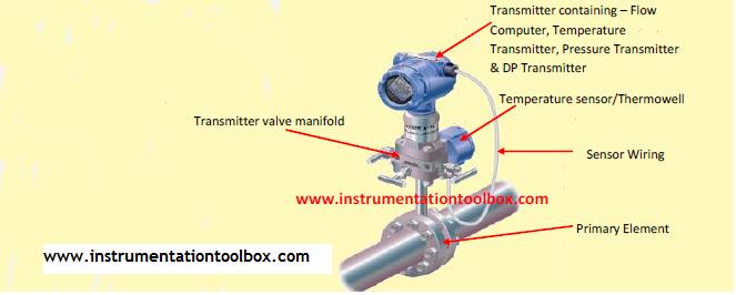
A multivariable transmitter is a differential pressure transmitter that is capable of measuring a number of independent process variables, including differential pressure, static pressure, and temperature. When used as a mass flow transmitter, these independent values can be used to compensate for changes in density, viscosity and other flow parameters. A typical multivariable transmitter installation and setup for flow measurement is shown below:
Multivariable Transmitter Installation & SetUp
A Multivariable transmitter delivers unprecedented performance and capabilities by providing three separate


How Pressure & Temperature Changes Affects Flow Meter Accuracy in Gas Flow Measurements

Custom Search

In gas flow measurement, the density of the gas changes as pressure and temperature change. This change in density can affect the accuracy of the measured flow rate if it is uncompensated. There are two exceptions however where uncompensated density change will not affect the flow measurement:
(1) A direct mass flow measurement made with a mass meter – coriolis or thermal mass.
(2) An actual volumetric flow measurement made by velocity type meters – Vortex, Turbine, Ultrasonic, Positive Displacement etc.

The accuracy of all other types of flow measurements are affected by changes in gas density.


Effect of Rangeability & Maximum Flow Rate on Accuracy of DP Flow meters

Custom Search

If you use DP flow meters then you must read this article. It is often believed that DP flow meters have low rangeability typically 3:1. However, with continuous improvement in measurement technology especially pressure transmitters, this assertion is now a myth rather than reality. For DP flow meters, low rangeability means large errors at low flow rates since flow is proportional to square root of differential pressure. Rangeability and maximum flow rates are critical factors that should be well understood before you can accurately specify a DP flow meter or any flow meter for that matter. Having a good understanding of the two concepts can help improve accuracy and increase rangeability of a meter in a given application.
To have a thorough understanding of the effect of rangeability and maximum flow rate has on the accuracy of a DP flow meter, we need to understand the following terms;
(1) Rangeability
(2) Maximum flow
(3) Percent of flow range


Basics of Permanent Pressure loss in Differential Pressure Flow Meters

Custom Search

The standard primary flow sensors commonly used in differential pressure flow meters are the orifice plates, flow nozzles and venturi tubes. These flow meters are often called "head loss" meters because there is a permanent pressure loss downstream these meters. In other words, upstream pressure never recovers to its original value downstream these meters. Various designs of these flow sensors are available which can provide the optimal meter for the desired operating conditions and requirements of the user. A critical factor in choosing a differential pressure flow meter is the pressure loss of the flow sensor. As a rule, when applying differential pressure devices, pressure loss must be small. This is because pressure loss means energy loss and higher pumping/compression costs.

The different installation versions of the primary flow sensors (orifice plates, flow nozzles, venturis) of differential pressure flow meters commonly used in flow measurement are tabulated below:


Flow Meter Selection Chart

Custom Search

Fluid flow rate is an important measurement in the process industries. Selecting an appropriate flow measurement technique can be a daunting task. Flow metering technologies tend to fall into four classifications: velocity, inferential, positive displacement, and mass. Among the common flow meters used to measure flow include:
(a) Mass flow meters
(b) Magnetic flow meters
(c) Positive Displacement flow meters
(d) Turbine flow meters
(e) Differential pressure flow meters
(f) Ultrasonic flow meters
(g) Swirl and Vortex flow meters
To aid in the selection of


Volume Flow Rate in Liquid and Gas Measurement

Custom Search


On this blog, we have discussed in the past various flow meter technologies where a volumetric flow rate is required. It is also important that we discuss the unit of flow measurement in some of these flow meter technologies. This post intends to increase your understanding of volumetric flow rates in liquid and especially gas flow measurements.

As we may have seen, the majority of flow meter technologies operate on the principle of interpreting fluid flow based on the velocity of the fluid. Some of the flow meter technologies using this principle include:
(a) Ultrasonic flow meters
(b) Turbine Flow meters
(c) Orifice Flow meters etc.

In these velocity-based flow meters, fluid velocity can easily be translated into volumetric flow by using the continuity equation below:

                               Q = AV
Where:
Q = Volumetric Flow rate
A = Cross-sectional area of flow meter throat
V = Average fluid velocity at throat section


Flow Instrumentation: Principles and Formulas

Custom Search

The measurement of fluid flow is arguably the single most complex type of process variable measurement in all of industrial instrumentation. This is because there are vast array of flow metering technologies that can be used to measure fluid flow each one with its own limitations and individual characteristics. Even after a flow meter has been properly designed and selected for the process application and properly installed in the piping, problems may still arise due to changes in process fluid properties (density, viscosity, conductivity), or the presence of impurities in the process fluid. Flow meters are also subject to far more wear and tear than most other primary sensing elements, given the fact that a flow meter’s sensing element(s) must lie directly in the path of potentially abrasive fluid streams.

Given all these difficulties and complications of fluid flow measurement, it becomes imperative for any end user of any given flow meter technology to understand the complexities of flow measurement. What matters most is that you thoroughly understand the physical principles upon which each flow meter depends. If the “first principles” of each technology are understood, the appropriate applications and potential problems become much easier to identify and solved.
Here some basic principles and common formulas used in flow instrumentation are introduced.


Flow Meters Accuracy and Terminology

Custom Search

Flow meters are very popular devices that help to determine the quantity of fluids through pipes at any given time. The majority of flow meters are applied in custody transfer applications where a seller of a given fluid –gasoline, natural gas etc needs to make sure that the actual quantity of fluid is being sold to a buyer and of course the buyer needs to ensure that he is getting value for his money by ensuring that he gets the actual quantity of fluid being paid for. Also in many industrial control applications, flow metering is critical to deliver control objectives.
So whatever the area of application of your flow meter, you need to understand the terminology used in flow meter specifications and also the accuracy level of the device. Now when it comes to flow meter accuracy, it can get a little tricky and even misleading if you don’t have a thorough understanding of the types of accuracy metrics flow meters manufacturers employ to define their products. A clear understanding of flow meter accuracy is therefore necessary if you must get your flow meter specifications right.


How Turbine Flow Meters Work

Custom Search

Turbine flowmeters are engineered to accurately measure the flow of liquids and gases in pipes. They measure flow on a volumetric basis. Turbine flowmeters are applicable to clean fluids over a pressure range from sub-atmospheric to over 6,000psi and temperatures from -450 to about 6000 degree Fahrenheit.
Turbine flowmeters produce output signals that are electronic pulses but other output signals – analog(4 – 20mA), visual or digital- are available.


The Basic Parts of a Turbine Flowmeter:


Turbine Housing
This houses the turbine rotor, shaft and bearings .Turbine meters housing are usually manufactured from stainless steel although turbine meters intended for municipal water service are bronze or cast iron. They are also available in a variety of other materials including plastic.


Flow Meter Selection Guide

Custom Search

One of the most important measurements made in an industrial plant is flow. How much quantity of a given fluid do you require to accomplish a given task? Or how much quantity of gasoline do you require to sell at the gas pump? Whether you are doing the flow meter selection in-house or a vendor or contractor is doing the selection for you, there are many factors you need to consider to successfully see this process through.
To select the right flow sensor or meter, you need to consider many important factors:


Mass Flow Meters

Custom Search

Measurements of mass flow are preferred over measurements of volumetric flow in process applications where mass balance (monitoring the rates of mass entry and exit for a process) is important. Whereas volumetric flow measurements express the fluid flow rate in such terms as gallons per minute or cubic meters per second, mass flow measurements always express fluid flow rate in terms of actual mass units over time, such as pounds (mass) per second or kilograms per minute.


Electronic Flow meters

Custom Search

As observed before now in: Theory of Fluid Flow meters, there are various classification of flow meters. No single classification is by any means exhaustive or sufficient if I may say. However, each classification attempts to present the flow meters in a logical grouping. The following flowmeters have been grouped as electronic flow meters:
(a) Magnetic Flowmeters
(b) Vortex Flowmeters
(c) Ultrasonic Flowmeters

They are not entirely electronic in nature but they represent a logical grouping of flow measurement technologies. All these meters have no moving parts(though they may experience vibration in operation). Their functionality is made possible through highly sophisticated electronic devices and circuits.


Mechanical Flow meters

Custom Search

Mechanical flowmeters measure flow by using an arrangement of moving parts, either by passing specific, known volumes of a fluid through a series of gears or chambers (in the case of positive displacement meters) or by means of a spinning turbine or rotor in an arrangement called a turbine flowmeter.


Positive Displacement Flowmeters 
Positive displacement flowmeters or PD meters operate by isolating and counting known volumes of a fluid (gas or liquid) while feeding it through the meter. By counting the number of passed isolated volumes, a flow measurement is obtained. Each PD meter has its own distinct mechanism that goes through a specific number of cycles for counting fluid volumes. Every cycle of the meter’s mechanism displaces a precisely defined (“positive”) quantity of fluid, so that a count of the number of mechanism cycles yields a precise quantity for the total fluid volume passed through the flowmeter. Many positive displacement flowmeters are rotary in nature, meaning each shaft revolution represents a certain volume of fluid has passed through the meter. Some positive displacement flowmeters use pistons, bellows, or expandable bags working on an alternating fill/dump cycle to measure off fluid quantities. Positive displacement flowmeters are applicable only to clean fluid flow streams.


You May Also Like: