
Custom Search
A valve positioner is a device used to increase or decrease the air load pressure driving the actuator of a control valve until the valve’s stem reaches a position balanced to the output signal from the process variable instrument controller.
Reasons for Using Valve Positioners
Typical Control Valve Configuration Without Positioner:

Positioners are generally mounted on the side-yoke or top casing of the pneumatic actuator for linear-sliding-stem control valves and at or near the end-of-shaft for rotary control valves. For either basic design type, the valve positioner is connected mechanically to the valve stem or valve shaft so that their position can be compared with the position dictated by the controller. This mechanical feedback linkage work in such a way that the process controller tells the positioner to “change” position; the feedback linkage reports back to the positioner confirming that a change in the position of the valve stem has occurred and gives a sense of the magnitude of the change in position. Note that for continuous control over the entire stroke of the valve, the use of positioners is usually necessary if the valve position is
required to closely follow the control signal.
required to closely follow the control signal.
However in some other applications where the feedback from the process is fast and proportional to the valve opening, the position feedback used by the positioner is not necessary and the valve can be driven directly by changing its actuating force directly from the process controller.
Reasons for Using Valve Positioners
The reasons for use of the valve positioner are summarized below:
(1) Increase control system resolution i.e. fine control
(2) Facilitate operation when the higher number in the actuator bench-set range is greater than 15psig. i.e. 10 – 30psig, 6 – 30psig
(3) Allow the use of characteristic cams in rotary valves
(4) Minimize valve stem packing friction effects and the resulting hysteresis, particularly for high temperature packing materials such as graphite
(5) Negate flow-induced reactions to higher pressure drops. i.e compensate for internal force imbalances
(6) Increased speed of response to a change in process; allows faster loading and venting.
(7) Allow for split ranging. i.e. one controller for two valves
(8) To overcome seating friction in rotary valves
(9) Allow distances between controller and control valve
(10) Allow wide range of flow variation. i.e. operate at less than 10% travel under normal conditions
(11) Allow increased usage of 4 – 20mA electronic signal
(12) Permit use of piston actuators with high instrument air supply pressures.
Types of Positioners
Positioners are available in three configurations:
Pneumatic Positioners
A pneumatic signal (usually 3-15 psig) is supplied to the positioner. The positioner translates this to a required valve position and supplies the valve actuator with the required air pressure to move the valve to the correct position. Note that the positioners used to articulate the principle of valve positioners here are pneumatic. Read How a Pneumatic Valve Positioner Works
Analog I/P Positioners
This positioner performs the same function as the pneumatic type, but uses electrical current (usually 4-20 mA) instead of air as the input signal.
Smart or Digital Positioners
Smart or digital positioners function very much as the analog I/P type described above, however it differs in that the electronic signal conversion is digital rather than analog. The digital products cover three categories namely:
(a) Digital Non-Communicating : In this type,a current signal (4-20 mA) is supplied to the positioner, which both powers the electronics and controls the output.
(b) HART : This is the same as the digital non-communicating but is capable of two-way digital communication over the same wires used for the analog signal.
(c) FieldBus: This type receives digitally based signals and positions the valve using digital electronic circuitry coupled to mechanical components. Here, an all-digital control signal replaces the analog control signal. Additionally, two-way digital communication is possible over the same wires. Fieldbus technologies benefit the end user by enabling improved control architecture, product capability and reduced wiring.
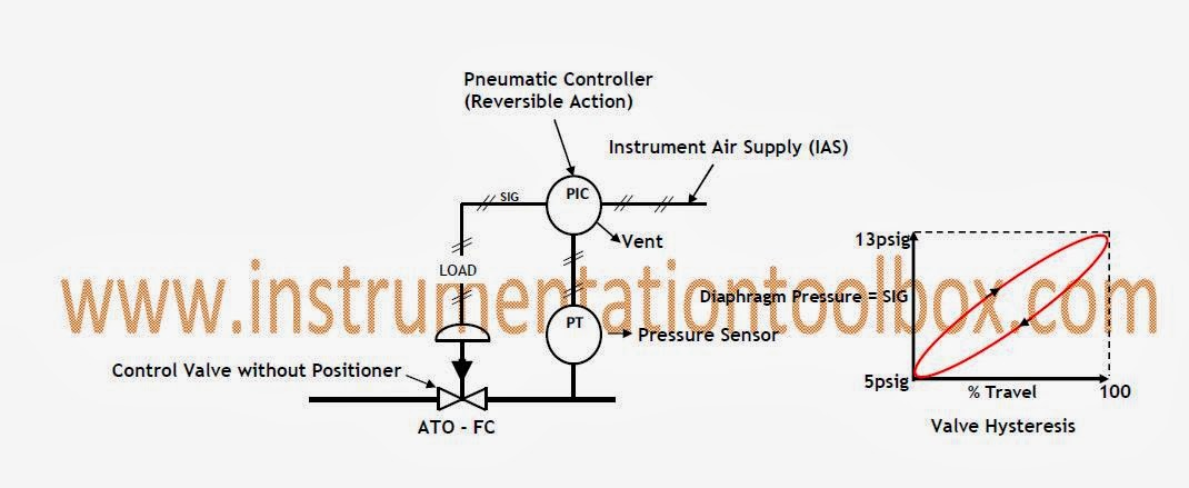
Typical Control Valve Configuration Without Positioner:
The diagram above is for a linear sliding stem control valve without a positioner. The valve has an actuator bench set of 5 – 13psig. As can be seen, the valve configuration is air to open, fail close (ATO –FC). Once the controller (PIC) outputs a control SIGNAL (designated SIG in the diagram above), the signal acts as the load pressure on the diaphragm actuator of the valve changes, resulting in valve stem travel. However, as can be seen from the plot of Diaphragm/SIG Pressure against % percent travel of valve, there is significant hysteresis throughout the valve stroke largely due to friction and forces of inertia within the valve. It should be noted above that the controller signal, SIG and the LOAD pressure on the actuator are the same flow stream. Actuator air flows through the pneumatic controller and the interconnecting tubing; air is vented through the controller. Due to the absence of a valve positioner, no stem position feedback.
Typical Control Valve Configuration with Positioner
The diagram above is for a linear sliding stem control valve with a positioner. The valve has an actuator bench set of 5 – 13psig. As can be seen, the valve configuration is air to open, fail close (ATO –FC). Here also there is a mechanical linkage between the valve stem and the positioner (V/P in the diagram above) providing stem position feedback to the positioner. As can be seen above, controller outputs a signal, SIG, which enters the positioner. With a valve positioner, the SIG and LOAD streams are separate. Actuator air flows through the valve positioner and its short interconnecting LOAD tubing. The pneumatic controller (PIC) air flows through the tubing interconnecting and the positioner, also called the SIG tubing.
The valve positioner provides “stem position feedback” to the control loop in that a change in controller SIG output forces a change in positioner LOAD output which results in a valve stem travel. The mechanical feedback linkage then “confirms” that travel occurred. If no travel is fed back to the positioner, positioner output will continue to change until stem travel is confirmed. The plot of positioner output/LOAD versus % valve travel shows that the hysteresis present is very small compared to the one without a valve positioner. Typically valve hysteresis with positioners is 5% of valve stroke.