Temperature sensors ~ Learning Instrumentation And Control Engineering Learning Instrumentation And Control Engineering

Temperature Controller Basics

Custom Search


Temperature Control Loop
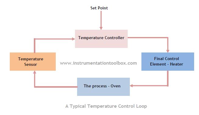
A simple temperature control loop consists of a sensor immersed in the process whose temperature is required to be controlled. The measured temperature is transmitted to a temperature controller which has a set point – set at the desired temperature – we want to keep our process at. When the temperature of the process is above or below the set point, the controller initiates a control action by giving an output which acts on


Temperature Sensors Selection Criteria

Custom Search

In the process industry Resistance Temperature Detectors (RTDs) and Thermocouples (T/Cs) are most common temperature sensors in use. When exactly should you use an RTD or a Thermocouple? Are their applications where a thermocouple is more suitable than an RTD or vice versa? Does accuracy level of my application determine which sensor to use? These and many other questions will be answered when you finish reading this article.

In the table below are some application questions that needs to be answered before you can successfully apply the right temperature sensor technology. When you are  able to provide the right answers to these application questions /selection criteria required, you will be in good stead to choose the right sensor for your application. The advice given below are only for guidance. Always consult the vendor for a specific temperature sensor application.

Application Question(s)/
Selection Criterion
Application Advice
What process are we measuring the   temperature?
  • To be able to select the appropriate temperature sensor, you must understand the process thoroughly
What is the process fluid concerned?
  • In most cases, temperature measurement is required for either gas, liquid, steam or granular fluids.
  • Understanding the nature of the fluid helps to select the best temperature sensor required
  • What is the operating pressure?
  • What is the maximum pressure in the system?
  • Knowing what the pressure level in the system where we need to measure temperature will give us the an idea of the right sensor to select.
What is the normal, maximum, and minimum fluid flow rate?
  • Flow rate is a key requirement in selecting a temperature sensor.
Will the measurement be taken in a pipe or vessel?
Is the pipe or vessel  full or partially filled?
  • The level of fluid in the pipe or vessel with enable the right sensor with the right probe length to be selected
What is the ambient temperature range around the measurement point?
  • Ambient temperature range will impact on sensor accuracy as we can easily predict the ambient temperature effect on the measurements taken from the sensor
Where will the measurement be taken? Ground level or elevated?
Is it desirable to have a local display of the temperature ?
  • Local display capability is good for operators in the field who can easily determine the temperature.
Are you monitoring temperature trend or an actual controlled value?
  • Trend monitoring requires little or no accuracy.
  • An RTD or a Thermocouple will do the job in this type of application
  • What is the temperature range of the application?
  • What is the control point?
  • What is the maximum and minimum temperature required for the application
  • If the maximum temperature to be measured is above 850°C, then a thermocouple is the only choice.
  • For most other applications, an RTD or a thermocouple would be fine.
Do you have established plant or company preferences that may influence your choice of temperature sensor?
  • If you use specific sensor types on specific applications based on successful experience, it will be wise to follow this trend.
  • However do not always follow this trend of we have always done it this way. Asking a few more questions and probing deeper will not hurt.
  • Most plants always use an RTD as the first choice temperature sensor unless  they are limited by high temperature requirement where a thermocouple becomes the obvious choice
Do you have certain temperature sensor types kept in your inventory?
  • Use only a normally stocked temperature sensor type if it meets the requirement for your application.
What is the stability and control precision requirement?
  • If accuracy requirement is far  better than ±20F, use an RTD.
  • If long term stability is required, an RTD is a better choice than a thermocouple
  • Spring  loaded wire wound designs for temperature sensors provide the best accuracy
What is the speed of response to temperature change requirement?
  • Spring loaded temperature sensors and stepped thermowells provide good speed of response.
  • Fill the voids between the temperature sensor and the inside bore of the thermowell to increase the speed of response.
Is there a significant return on investment (ROI) for best possible accuracy and stability?
  • If you are dealing with an application such as custody transfer where improved accuracy can yield significant ROI, consider using an RTD.
  • Use an RTD with sensor-transmitter matching option for system accuracy as good as 0.015 °C 
What costs are associated with temperature measurement failure?
  • Measurement failure most often results in production down time costs, off-spec products that may require re-processing or selling at a reduced price; energy inefficiency; dangerous runaway reactions etc.
  • To avoid the above costly consequences, use a high quality transmitter integrally mounted with a quality sensor
  • A high quality RTD will suffice where measurement failure could trigger serious financial consequences
  • What is the frequency and severity of the piping and vessel vibration?
  • What is the typical and maximum vibration trend?
  • High vibration requires the use of a thin film spring loaded RTD sensor.
  • In some applications, a helical coil wire wound RTD will perform better.
  • A heavy gauge thermocouple is a possible alternative.
  • Where in doubt, consult vendor product data sheets for specifications.
Is the temperature measurement part of a safety instrumented system (SIS)?
  • Where an SIS system is involved, use the highest possible quality of sensor and reliability system


How A Thermostat Works

Custom Search

 
The schematic of a simple rod thermostat is shown above. The thermostat comprises two elements – Brass and Invar - that expand at different rates. The brass tube expands a lot as it gets hotter but invar expands very little.  When the liquid whose temperature we want to control is cool the brass does not expand so the switch is closed and the electric heater heats the water.  When the water reaches the set temperature, the brass tube has expanded enough to pull the Invar rod away from the switch.  This opens the switch and breaks the circuit.

The electric heater will stay disconnected until the brass tube contracts enough to close the switch again.  Normally the thermostat and heater are together in one unit.  The temperature at which the switch is opened can be adjusted by changing the tension of the spring which closes the switch.  Thermostats are not very accurate ( ± 30 degree C) but they are long lasting and cheap.


How a Temperature Control Loop Works

Custom Search

A temperature control loop is designed to measure and control the temperature of a process.  A typical process whose temperature is required to be controlled is an Oven which has a heater. Another very common process in the home is water bath temperature in a water heater whose temperature is controlled by a thermostat.


Basic Elements in a Temperature Control Loop:
As shown above, there are four basic components of


How Temperature Switches Work

Custom Search

A temperature switch works just like a typical electrical switch for on /off application. In this case, the temperature switch operates to switch on or off at discrete process temperatures. A temperature switch consists of two basic parts that you will find in all designs:
(a) A sensing part immersed in the process whose temperature is required to be controlled. The sensing part can either be a sensing bulb filled with a fluid –liquid, gas or a bimetallic strip that uses the differential expansion of two dissimilar metals.
(b) Snap-action contacts that act to switch on electrical power to the device controlling process temperature.

How a Temperature Switch Works
Liquid filled temperature switches comprises a sensing bulb and a bellows element. The bulb is immersed in the process whose temperature is being controlled. The bellows element senses fluid pressure (liquid or gas)


How to Convert Resistance to Temperature

Custom Search

Resistance is the electrical property of a material that opposes the flow of electricity through it. This degree of resistance to electricity is defined by another property of the material called Resistivity.
The resistivity of a material is defined as the resistance to current flow between the opposite faces of a unit cube of the material (ohm per unit length). Hence the resistance R of a component is expressed by:

R = ρL/A

Where:
R = Resistance of the component in Ohms
L = Length of the component
A = Cross sectional Area of the component
ρ = Resistivity of the material
To use the above formula, L and A must be in compatible units


How a Temperature Transmitter Works

Custom Search


A temperature transmitter combines a temperature sensor – RTD or Thermocouple and a transmitter in the same instrument. The sensor measures the temperature while the transmitter amplifies and transmits the signal to the monitoring system or a control room. A temperature transmitter measures temperature and converts it into


How to Use a Thermocouple: Practical Application Tips

Custom Search

A thermocouple is said to be a ‘’simple’’ temperature measurement device. With a difference in temperature between its cold junction and hot junction, you have a voltage reading that gives you an indication of the temperature being measured. But is this really a simple device?


Factors to Consider When Selecting a Thermocouple for Temperature measurement Application.

Custom Search


There are many different types of thermocouples. Each has its advantages and disadvantages over other types of thermocouples that you may find in the market. Some of the factors to guide your selection of thermocouple for any given applications are discussed below.


How to Convert Thermocouple Milivolts to Temperature

Custom Search


The voltage generated by thermocouples is very small. They are in the order of milivolts. In the application of thermocouples to measure temperature, it is often required to convert the milivolts signals of thermocouples to temperature values. To aid this conversion, several milivolts voltages for the different types of thermocouples are tabulated against known standard temperatures. With these thermocouple reference tables, it is then easy to determine any given temperature for known milivolts values.

Thermocouple reference tables are based on a reference junction of 0 degree C. If the reference junction is not at 0 degree C, then a correction factor must be applied.
Calculating Temperature from Voltage (reference junction = 0 degree C)
The steps involved are:
  • Select the correct reference table for the thermocouple type in use. e.g. J,S,T etc
  • Locate the milivolt reading in the body of the table, and read from the margins the temperature value.
Note that the temperature determined from a particular thermocouple reference table only gives accuracy to that of the increments on the scale in the table. For more accurate measurement,


Reducing Noise In Thermocouple Installations

Custom Search


As you may already know, a thermocouple is formed by joining two different metal alloys at a point called a junction. This junction is called the measuring or hot junction. The thermocouple leads are usually attached to a temperature indicator or controller. This connection point is called the reference or cold junction.

When the measuring junction is heated, a small DC voltage is generated in the thermocouple wires. The temperature controller measures the small voltage signal and converts it to a temperature reading. However, the voltage generated in the thermocouple is so small that


How to Convert RTD Resistance to Temperature

Custom Search

An RTD resistance can be converted into temperature using standard tables that gives values of temperatures for any given resistance value of the RTD.
The table below shows temperature versus resistance data in degree celsius with temperature coefficient of resistance of: 0.003916 ohm/ohm/°C.


How to Specify an RTD Sensor

Custom Search

When a Resistance Temperature Detector (RTD) is required for a given application, many parameters need to be accurately documented for the particular RTD to be procured from the manufacturers. Since there are many different manufacturers of RTDs, there will be several different styles of RTDs in the market. Each manufacturer has their own way of specifying their product. In any case, when specifying an RTD you will always be required to select the following:


Comparison of The Common Temperature Sensors

Custom Search

Semiconductor Temperature Sensors:
Semiconductors have a number of parameters that vary linearly with temperature and they form the core of today’s electronic temperature sensors. Normally the reference voltage of a zener diode or the junction voltage variations are used for temperature sensing. Transistors or diodes can also be used for temperature measurement. The outputs of these semiconductor devices are very linear and are good for


Resistance Temperature Detectors(RTDs): Application limitations, Comparison of types and Failure mode

Custom Search

Application Limitations of RTDs:
RTDs can be quite bulky, which can inhibit their use in applications.Self heating can be a problem with RTDs. In order to measure the resistance of an RTD device, we must pass an electric current through it. Unfortunately, this results in the generation of heat at the resistance according to Joule’s Law:
 P = I2 R 
                                                                 
This dissipated power causes the RTD to increase in temperature beyond its surrounding environment, introducing a positive measurement error. The effect may be minimized by


RTD Construction and Lead Wire Configurations

Custom Search


Platinum RTD elements are available in two types of constructions:
(a) Thin film and

(b) Wire wound.

Thin Film
Thin-film RTD elements are produced by depositing a thin layer of platinum onto a substrate. A pattern is then created that provides an electrical circuit that is trimmed to provide a specific resistance. Lead wires are then attached and the element coated to protect the platinum film and wire connections.
Thin film elements are available in the.

European standard (0.00385 Ω/Ω/°C), and in a special version, used primarily in the appliance industry, that has a temperature coefficient of 0.00375 Ω/Ω/°C. Thin film elements are not available in the American standard.

Wire Wound:
RTD elements also come in wire-wound constructions. There are two types of wire-wound elements:

(a)Those with coils of wire packaged inside a ceramic or glass tube(the most commonly used wire-wound construction), and

(b)Those wound around a glass or ceramic core and covered with additional glass or ceramic material (used in more specialized applications).

Wiring Arrangement of RTDs:
-->
In order to measure temperature, the RTD element must be connected to some sort of monitoring or control equipment. Since the temperature measurement is based on the element resistance, any other resistance (lead wire resistance, connections, etc.) added to the circuit will result in measurement error. The four basic RTD element wiring methods according to the IEC/ASTM color  codes are:
(a) 2 Wire configuration
(b) 3 Wire configuration
(c) 4 Wire configuration
(d) 2 Wire configuration with compensating loop.

2 Wire configuration RTD:

This wire configuration provides one connection to each end of the RTD sensor. This construction is suitable where the resistance of the run of lead wire may be considered as an additive constant in the circuit, and particularly where the changes in lead resistance due to ambient temperature changes can be ignored. This wire configuration is shown below:


Note that the resistance of probe and extension is added to the RTD resistance and will increase the measured value. This could be a source of error in applications where high accuracy is required.
 
3 Wire Configuration RTD:
This is the standard wire configuration for most RTDs. It provides one connection to one end and two to the other end of the RTD sensor. Connected to an instrument designed to accept three-wire input, compensation is achieved for lead resistance and temperature change in lead resistance. This is the most commonly used configuration.


4 Wire Configuration RTD:
This wire configuration provides two connections to each end of the RTD sensor. This construction is used for measurements of the highest precision.


2 Wire Configuration RTD with Compensating Loop:
This is similar to 4 wire configuration RTD except that a separate pair of wires is provided as a loop to provide compensation for lead resistance and ambient temperature changes in lead resistance. 

For more information on RTD Sensors, check out:


Bi-Metallic Temperature Sensors

Custom Search

Solids tend to expand when heated. The amount that a solid sample will expand with increased temperature depends on the size of the sample, the material it is made of, and the amount of temperature rise. The following formula relates linear expansion to temperature change:


Thermistors

Custom Search

Thermistors are devices made of metal oxide semi-conductor material which either increase in resistance with increasing temperature (a positive temperature coefficient) or decrease in resistance with increasing temperature (a negative temperature coefficient). Their resistance changes a lot for a small change in temperature and so they can be made into a small sensor and they cost less than platinum wire RTDs. The major difference between thermistors and RTDs is


Filled Bulb Temperature Sensors

Custom Search

Filled-bulb systems use the principle of fluid expansion to measure temperature. If a fluid is enclosed in a sealed system and then heated, the molecules in that fluid will exert a greater pressure on the walls of the enclosing vessel. By measuring this pressure, and/or by allowing the fluid to expand under constant pressure, we may infer the temperature of the fluid.
There are basically four types of filled bulb temperature sensors in use in industrial applications. They are:


Thermowells

Custom Search


The process environment where temperature monitoring is required is often not only hot, but also pressurized and possibly chemically corrosive or radioactive. To facilitate removal of the temperature sensors (RTD and Thermocouple), for examination or replacement and to provide mechanical protection, the sensors are usually mounted inside thermal wells widely referred to as a thermowell in the industrial environment
What is a Thermowell?

A thermowell is basically a hollow metal tube with one end sealed. It is usually mounted permanently in a vessel or pipe work. The sensor is inserted into it and makes contact with the sealed end. 
A simple diagram showing a thermowell in use with a temperature gauge is shown below:


You May Also Like: