~ Learning Instrumentation And Control Engineering Learning Instrumentation And Control Engineering

Instrument Air System Design, Sizing and Distribution

Custom Search

 Design of Instrument Air System

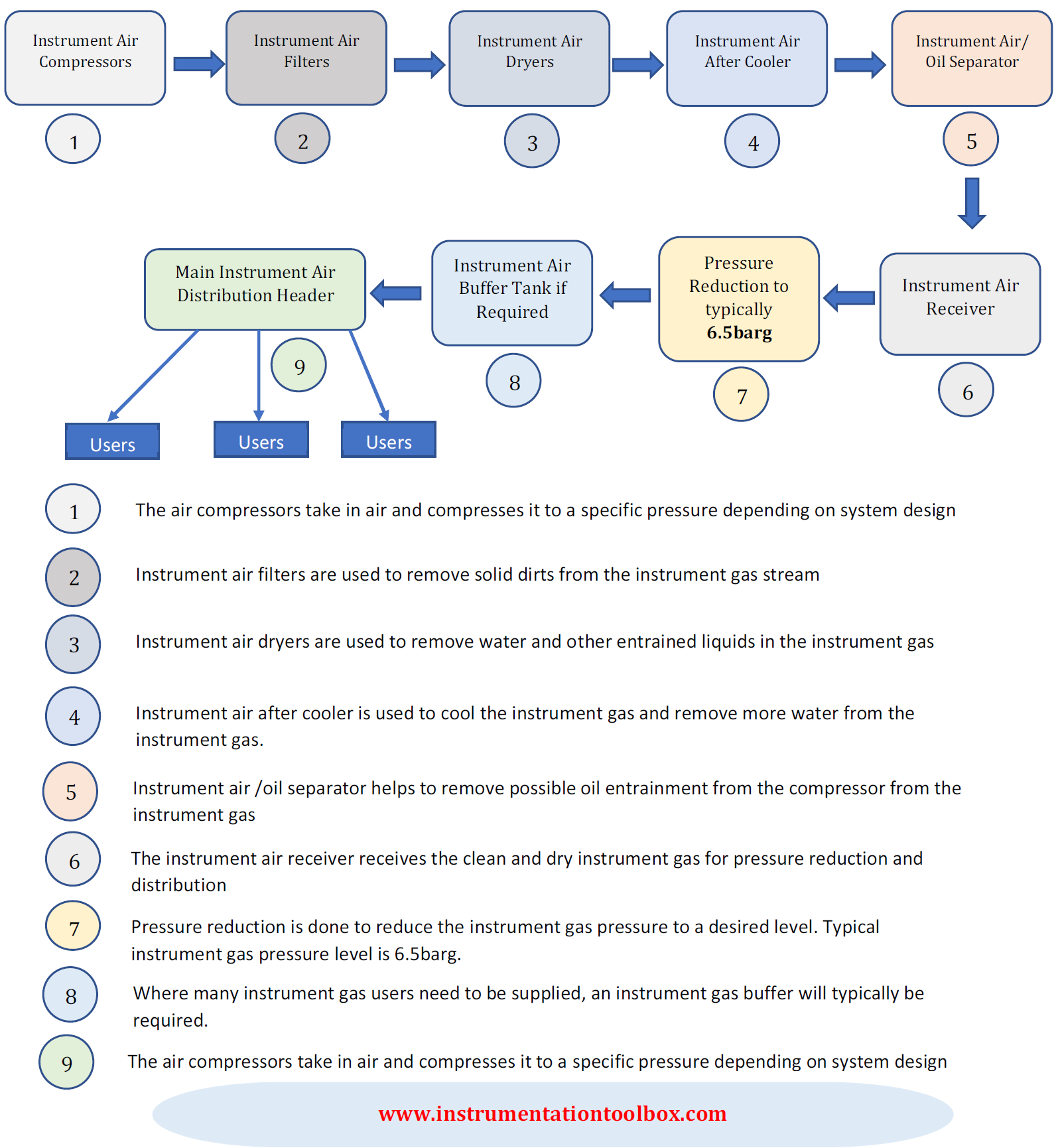
Every plant requires instrument air system for some form of pneumatic control. The design of the design, sizing and distribution of instrument air is different from plant to plant depending on the location, the environment, and the number of instruments to be supplied instrument gas.

Below is illustrated a typical instrument air system design that you will find in a typical plant. Note that the blocks 1 to 5 illustrated in the schematic below are typically part of a vendor package. The vendor supplies these units as a package:
Sizing and Distribution

Normally, instruments in the unit requiring an air supply will be fed from carbon steel air headers or sub-headers.  Take-off valves in all Unit areas will be provided by piping on the instrument air main header. 

These take-off valves will be installed at each rack column. Connections to instrument air main headers will always be at the upper section of the pipe. Branch-off points for future extensions in an instrument main header will be provided with an isolating valve and plug. 

The sub-headers will be provided with drain valves at low point and at dead ends and are to be sized in accordance with the following table:

No. of Instrument Air Users

Nominal Diameter

1-6

1/2"

7-12

3/4"

13-25

1"

26-50

1 1/2"

51-100

2"


Recommended Practice in the Use of Orifice Plates

Custom Search

Orifice plates are the most common flow device you will find in any process plant. Although not very high in accuracy but they are rugged, have low maintenance cost and have been applied successfully in process instrumentation to measure flow. 

Listed in the table below are recommended practices when it comes to industrial application of Orifice plates:


Recommended Practice in the Use of Orifice Plates

1

Orifice plates, with flange taps, square edge and concentric orifice are normally used on pipe sizes from 2” and above.

2

Eccentric or Segmental orifice plates are typically specified on fluids with suspended solids, sediments and on biphasic streams.

3

Quarter Circle orifice plates are typically specified for high viscosity fluids with a Reynolds number between 2500 and 10000.

4

The full-scale value for measurements is normally selected equal to the maximum flow rounded off at 1-5 % above or adjusted to 1.2 times the normal operating flow if the maximum flow is unknown.

5

Standard calibrated ranges of differential pressure are typically used for the calculation with a preference for 250 mbar.

6

The recommended values of Beta ratio will be selected within 0.2 - 0.75, preferably between 0.4 – 0.75.

7

Orifice bore will be rounded off to the nearest 0.1 mm.

8

Bleed and vent holes are usually specified for orifice plates in horizontal pipe and with a bore diameter of at least 20 mm. 

9

Orifice plates for pipe sizes of ½”, ¾”, 1” and 1”1/2 are usually installed between flanges in meter runs prefabricated.

10

Meter sections will be preferably flanged. Meter runs and relevant orifice bores are usually sized using the Manufacturer proprietary algorithms.


Instrument Ranges Used in Process Control System Design

Custom Search

In process control design process variables such as temperature, pressure, flow, level, valve signals, analyzers etc are ranged in such a manner to be proportional to the primary signal as much as possible for control purposes. The table below shows the typical instrument scales employed in process control system design:

Instrument Variable

Scale

Temperature

Direct Reading

Pressure

Direct Reading

Flow (differential)

0 – 100 linear

Flow (Linearized)

0 – 100 linear

Level

0 – 100 linear

Analyzer

Direct Reading

Signal to Valves

0 – 100%

As far as possible, the instrument ranges will be selected such that the normal value will be between 50 and 75% of the adjusted range taking into account the specified minimum and maximum values and trip settings will lie between 10% and 90% of the adjusted range.

Typical accuracy of the pressure and differential pressure Smart transmitters will be +/- 0.25% of the calibrated span.

Typical accuracy of temperature Smart transmitters will be +/- 0.3% of the calibrated span.

Typical accuracy of the other transmitters will be as far as possible better than +/- 0.5%.


Best Practice for the Selection of Types of Protection in Hazardous Areas For Process Instruments

Custom Search

 All installed process instruments in hazardous areas are required to have a type of protection that ensures safety of personnel as well as that of the instruments.

The following table provides the guidelines to select the type of protection according to the zone of risk:

Type of Protection

Meaning

Ex i

Intrinsic Safety

Ex d

Flameproof Enclosure

Ex e

Increased Safety

Ex m

Encapsulation

Ex p

Pressurized Apparatus


Device

Zone 0

Zone 1

Zone 2

Transmitter/Positioner

Ex i

Ex i (preferred)

Ex d (alternative)

Ex i (preferred)

Ex d, Ex e, Ex m (alternatives)

Switch/Push-Button

-

Ex de

Ex i (preferred)

Ex e, Ex m (alternatives)

Temperature Sensor

-

Ex e

Ex e

Solenoid Valve

-

Ex d

Ex d

Junction Box

-

Ex e

Ex e

Fire & Gas Detector

-

Ex d

Ex d

Analyzer

-

Ex I, Ex d

Ex i, Ex d

Local Panel

-

Ex d or Ex p

Ex d or Ex p


Note: As the Directive ATEX 94/9/EC is mandatory, only “Ex” equipment CE marked compliant with this ATEX Directive may be installed within the European Union.

Instruments will typically be designed to have immunity for radio frequency and electromagnetic interferences.


Control Valve Actuators Failure Modes

Custom Search

Control valves can be built from various combinations of valve actuator and valve body. The combination of actuator and valve body is usually chosen to provide a particular failure mode should the instrument air supply fail for any reason.
The most common control valve actuator used in the industry is the diaphragm actuator. Diaphragm actuators, as in the case of valve bodies, can be classified as either direct or reverse acting. 


Any failure mode can be obtained with a combination of direct or reverse acting
actuator and direct or reverse acting valve body. The two most common failure mode of control valves are :

1. Fail Open
2. Fail Close

These two failure modes can be achieved by an Air to Close Valve (ATC) and an Air to Open valve (ATO).

Air to Close Control Valve (ATC)
An air to close (ATC) valve and therefore fail open valve, can be obtained with the combination of a reverse acting actuator and a reverse acting valve body or a direct acting actuator and a direct acting valve body.

Air to Open Control Valve (ATO)
An air to open (ATO) valve and therefore fail close valve, can be obtained with a combination of direct actuator and reverse body or reverse actuator and direct Body.

Valve Body and Actuator Combination and Their Failure Modes
The action of an actuator can easily be determined (usually by whether the air is supplied to the upper or lower half of the housing). Direct or reverse acting valve bodies are not always readily identifiable. Most often, reference to the nameplate or flow sheet is usually necessary to correctly identify the action of a valve body – reverse acting or direct acting.

Listed in the table below are all possible combinations of valve body and actuator and their failure modes:

Valve Actuator 
Valve Body
Valve Action
Failure Mode
Direct 
Direct
Air to Close
Fail Open
Reverse
Reverse
Air to Close
Fail Open
Direct
Reverse
Air to Open
Fail Closed
Reverse
Direct
Air to Open
Fail Closed


Basics of Split-Range Control in Control Valve Applications

Custom Search

In many process control applications in industry, it is sometimes desirable to have multiple control valves respond to the output of a single common controller. Control valves configured in this way to follow the command of a single controller are said to be split-ranged, or sequenced.

Split-ranged control valves may assume different forms of sequencing. Common modes of control valve sequencing seen in the process industry are:  complementary, exclusive, and progressive.

Complementary Split-Range Control
With this form of split-ranging, there is never a condition in the controller’s output range where both valves are fully open or fully shut. Rather, each valve complements the other’s position.  A typical example of complementary split-range control is a situation where two valves serve to proportion a mixture of two fluid streams, such as where base and pigment liquids are mixed together to form colored paint as shown below:
Example of complementary split-range control.


Both base and pigment valves operate from the same controller output signal. While the pigment valve is Air-To-Open, the base valve is Air-To-Close. The following table shows the relationship between valve opening for each control valve and the controller’s output:
Controller Output (%)
I/P Output (PSI)
Pigment Valve (Stem position)
Base Valve (Stem position)
0
3
Fully Closed
Fully Open
25
6
25% Open
75% Open
50
9
Half-Open
Half - Open
75
12
75% Open
25% Open
100
15
Fully Open
Fully Closed

Exclusive Split-Range Control
The nature of valve sequencing in this type of split-range control is to have an “EITHER OR” throttled path for process fluid. That is, either process fluid flows through one valve or through the other, but never through both at the same time.

This type of split-ranged control valves call for a form of valve sequencing where both valves are fully closed at a 50% controller output signal, with one valve opening fully as the controller output drives toward 100% and the other valve opening fully as the controller output goes to 0%.

A practical example of this form of split-ranging is in reagent feed to a pH neutralization process, where the pH value of process liquid is brought closer to neutral by the addition of either acid or caustic:
Exclusive Split-Range Control

The basic operating principle of the above process is:
  1. A pH analyzer monitors the pH value of the mixture and a single pH controller commands two           reagent valves to open when needed.

  2. If the process pH begins to increase, the controller output signal increases as well (direct action)         to open up the acid valve.

  3. The addition of acid to the mixture will have the effect of lowering the mixture’s pH value.

  4. Conversely, if the process pH begins to decrease, the controller output signal will decrease as      well, closing the acid valve and opening the caustic valve.

  5. The addition of caustic to the mixture will have the effect of raising the mixture’s pH value.
The Air-To-Open acid valve has an operating range of 9 to 15 PSI, while the Air-To-Close caustic valve has an operating of 9 to 3 PSI. The table below shows the relationship between valve opening for each control valve and the controller’s output:

Controller Output (%)
I/P Output (PSI)
Acid Valve (Stem position)
Caustic Valve (Stem position)
0
3
Fully Closed
Fully Open
25
6
Fully Closed
Half - Open
50
9
Fully Closed
Fully Closed
75
12
Half - Open
Fully Closed
100
15
Fully Open
Fully Closed

Progressive Split-Range Control
This form of split-range control for control valves is used to expand the operating range of flow control for some fluid beyond that which a single control valve could deliver. In this type of control, one of the valve usually a small valve opens gradually and becomes fully open at 50% of controller output while the large valve will remain shut at until the controller output goes beyond 50% when it starts opening. Both valves become fully open when controller output is 100%.

An example of progressive split-range control is a pH control process where the incoming liquid always has a high pH value, and must be neutralized with acid as shown below:
An example of progressive split-range control

The PH of the incoming water to be treated is measured by the analyzer, AT. As the output of controller AIC increases, the small acid valve starts to open and becomes fully open at 50% of controller output. Meanwhile the large acid valve will remain shut until controller output goes beyond 50%. At 100%, both small and large acid valves are fully open to ensure that the PH of the incoming water is neutralized.

Controller output and valve status for proper sequencing of the small and large acid control valves is shown below:

Controller Output (%)
I/P Output (PSI)
Small Acid Valve (Stem position)
Large Acid Valve (Stem position)
0
3
Fully Closed
Fully Closed
25
6
Half Open
Fully Closed
50
9
Fully Open
Fully Closed
75
12
Fully Open
Half Open
100
15
Fully Open
Fully Open


You May Also Like: