
Custom Search
Pneumatic systems are characterized by the simplicity of the technology on which they are based and the relative ease with which they can be installed, operated, and maintained. They are based on the use of a flapper and nozzle system in conjunction with a pneumatic relay (essentially a pneumatic amplifier) to detect a very small relative movement typically less than 0.01 mm and to control a supply of compressed air so that a considerable force can be generated under precise control.
How a Flapper Nozzle System Works in Pneumatic Instruments
A typical flapper/nozzle system is shown below.
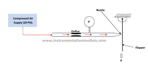
With the nozzle covered by the flapper, the pressure approaches the supply pressure, but when the flapper moves away from the nozzle the pressure falls rapidly to a value determined by the relative values of the discharge characteristics of the nozzle and the Orifice (restrictor). This variation in the back pressure P shown in the figure above with the flapper/ nozzle movement is shown below:
| Variation of Nozzle back pressure with Flapper movement |
This flapper nozzle system is the main stay of most pneumatic instruments. In a typical pneumatic instrument, the back pressure developed by the flapper nozzle movement is used to measure process pressure and other parameters in pneumatic instruments. A typical way to achieve this in pneumatic instrumentation is shown below.
How a 3 - 15psig Signal is generated in Pneumatic Instruments
 |
| How a 3 - 15psig is generated in pneumatic instruments |
With process pressure sensed at the input bellows which causes the flapper to cover the nozzle and increase the back pressure P with increasing process pressure. A range and bias spring (S) is used to limit the bellows travel and establish reference conditions of output and input process. In this way, 3 - 15psig output signal proportional to the process input signal is generated. This is just a variant to illustrate how a 3 - 15psig is generated in pneumatic instruments. There are other sophisticated systems used but the underlying principle remains the same.
How a Pneumatic Relay Works
For measurement purposes the back pressure generated by the flapper nozzle system is usually amplified, and this is effected by means of a pneumatic relay.
 |
| Foxboro Type of Pneumatic Relay |
As shown above, the pneumatic relay comprises two chambers separated from each other by a flexible diaphragm that has a conical seat and a stem that act as a valve to cover or uncover the exhaust port. The stem acts against a small ball retained by the leaf spring so that it functions as a second valve which controls the flow of air from the supply to the output port.
During operation when the nozzle is covered, the pressure in the associated chamber builds up, causing the conical valve to close the exhaust port and the ball valve to allow air to flow from the supply to the output port so that the output pressure rises. When the nozzle is uncovered by movement of the flapper the flexible diaphragm moves so that the ball valve restricts the flow of air from the supply. At the same time the conical valve moves off its seat, opening the exhaust so that the output pressure falls. In this way, the output pressure is driven from 20 3 to 15 pig (20KPa to 100KPa) as a result of the relative movement between the flapper and nozzle system