2015 ~ Learning Instrumentation And Control Engineering Learning Instrumentation And Control Engineering

How to Adjust the Bench Set of a Control Valve Actuator

As already explained in Control Valve Actuator Bench Set and Valve Stroking, the bench set of a control valve is the pressure range required to stroke the valve from a fully closed to a fully open position.
The bench set pressure range is used to adjust the initial compression of an actuator spring with the valve assembly “on the bench” The correct initial compression is important for the proper operation of the valve-actuator assembly when it is put into service and the proper actuator diaphragm operating pressure is applied.

The bench set range is established with the assumption that there is no packing friction. Accurate adjustment to the bench set range can easily be made during actuator mounting process by making the adjustment before the actuator is connected to the valve assembly.

When attempting to adjust the spring in the field, it is very difficult


How to Calibrate a Rosemount 1151 Pressure Transmitter

Calibrating the Rosemount Model 1151 Pressure Transmitter is simple and easy. With the aid of an accurate pressure source, an output meter, a power source and external span and zero buttons on the transmitter, the device can easily be calibrated. The zero and span adjustment screws are accessible externally behind the nameplate on the terminal side of the electronics housing. To calibrate the transmitter, setup the equipment required - pressure source, Rosemount 1151 pressure transmitter, Current meter to measure current output from transmitter, power source, pressure gauge (covering the LRV and URV of transmitter), a 250 ohm resistor if necessary for communication with transmitter - as shown below:
 

The output of the transmitter increases with clock wise rotation of the adjustment screws. The zero adjustment screw does not affect


How to Install Pressure Transmitters –Best Installation Practices

Installing a pressure transmitter or a differential pressure transmitter is suppose to be a simple process but can become a problem if certain best practices are not imbibed. One critical aspect of transmitter installation is the impulse piping between the process and the transmitter.

The piping between the process and the transmitter must accurately transfer the pressure to obtain accurate process measurements otherwise measurement error will occur and compromise the process. There are five possible sources of error in any given pressure transmitter installation. They are:
(a) Pressure transfer leaks
(b) Friction loss
(c) Trapped gas in a liquid line
(d) Liquid in a gas line
(e) Density variations between high pressure and low pressure impulse lines

The best location for the pressure transmitter


How to Zero a Pressure Transmitter – Three and Five Valve Manifolds Operation

I had discussed previously on DP Transmitter Valve Manifolds where I explained how to remove a transmitter from active service using 3 and 5 – Valve manifolds but zeroing a transmitter is slightly different.
Zeroing a transmitter involves bringing the transmitter to zero signal but does not remove the transmitter from service.The most popular transmitter manifolds are either a 3 or 5-Valve manifold and the operations involved in zeroing a transmitter using these manifolds are different.

How to Zero a Transmitter with a 3-Valve Manifold
Each step involved will be illustrated with a diagram. It is important to realize that over-pressure or transmitter damage could occur if the steps are not properly followed:
Under normal operation


Rules of Thumbs for Sizing Control Valves

In many applications where control valves are applied, sizing and selection can be quite challenging. In the majority of applications, it is either the control valve is under sized or over-sized. In an undersized control valve, the valve is unable to deliver the required flow for each stage of the valve lift creating control problems.

Over-sized control valves will under all normal operations be confined to small openings of the valve with great risk of variable sensitivity and aggravation of any uneven movement of the valve and actuator combination. Poor accuracy and unstable control are often the result of over-sized control valves.

Given the problems that could arise because of failure to size control valves accurately, the following rules of thumb are presented as a guide for the selection and sizing of control valves:


How a Temperature Control Valve Works

A temperature control valve is just like any other control valve. The only difference is that the control valve helps to maintain the temperature of a desired process at a specific level. It is often abbreviated as TCV – Temperature Control Valve – in most process drawings and P&IDs.

Temperature Control Schemes
There are two popular temperature control schemes using temperature control valves:
(1) Mixing of a cold process fluid with a hot process fluid to control the temperature of the hot process fluid.
(2) Exchange of heat between the hot process fluid and a cold process fluid as seen in heat exchangers. However, the process fluids do not mix.

Mixing of Cold and Hot Process Fluids
In temperature control valve applications in its most basic form, there are two basic process fluids:


How Temperature Switches Work

A temperature switch works just like a typical electrical switch for on /off application. In this case, the temperature switch operates to switch on or off at discrete process temperatures. A temperature switch consists of two basic parts that you will find in all designs:
(a) A sensing part immersed in the process whose temperature is required to be controlled. The sensing part can either be a sensing bulb filled with a fluid –liquid, gas or a bimetallic strip that uses the differential expansion of two dissimilar metals.
(b) Snap-action contacts that act to switch on electrical power to the device controlling process temperature.

How a Temperature Switch Works
Liquid filled temperature switches comprises a sensing bulb and a bellows element. The bulb is immersed in the process whose temperature is being controlled. The bellows element senses fluid pressure (liquid or gas)


How to Measure Control Valve Deadband

What is Deadband ?
Dead band can be caused by packing friction, unbalanced forces and other factors in the control valve assembly. In technical terms, control valve deadband is the range a measured signal can vary without initiating a response from the actuator. The schematics below illustrates the concept of deadband for direct and reverse acting control valve actuators:

Every control valve actuator has


Sizing Turbine Flow Meters And Best Design & Installation Practice.

 Selection and Sizing of Turbine Flowmeter
When selecting and sizing Turbine flow meters, the guide listed below can help in ensuring that the right meter is selected and correctly sized for your application: 

(a) Turbine Flowmeters are sized by volumetric flow rate; however the main factor that affects the meter is viscosity. Viscosity affects the accuracy and linearity of turbine meters. It is therefore important to calibrate the meter for the specific fluid it is intended to measure. Repeatability is generally not greatly affected by changes in viscosity.

(b) Turbine meters are specified with minimum and maximum linear flow rates that ensure the response is linear and the other specifications are met. For good Rangeability, it is therefore recommended that


Ultrasonic Flow Meters in Gas Flow Measurement – Application limitations & Best Practices

All flow measurement technologies have their individual limitations that impact on flow measurement accuracy. It is therefore important for engineers and technicians who use any flow measurement technology to consider the limitations of the flow meter proposed for use in a particular application before installation.
Below are the key factors which affect flow measurement accuracies in Ultrasonic meters used in custody applications for gas measurement:
1. Noise
2. Accumulation of Dirts and Liquids
3. Profile Distortions

Noise in Ultrasonic Flow Measurement
Ultrasonic flow measurement depends on accurate transit time measurement of sonic pulses. Noise inside the pipe work especially from fittings – valves, tees etc- can interfere with the detection of sonic pulses if the noise is of coincident frequency with the meter’s transducers and drown out the sonic pulses if it is sufficiently high in amplitude. Once pulses are drowned out, detection and therefore pulse transit time measurement becomes impossible and flow measurement practically stops.

Best Practices that Reduce Meter Errors due to Noise
1. Install Ultrasonic meters upstream of regulating devices
2. Locate the noise attenuating elements between meter and the noise source
3. Consult the meter manufacturer for meters of alternative frequency


Ultrasonic Flow Meters – Operating principle

Ultrasonic Meters have undergone a lot of improvement and development over the years and have transitioned from the engineering lab to wide commercial use. It is fast becoming the primary device of choice to measure gas volume for fiscal metering.

Types of Ultrasonic Meters
Inline Systems
Ultrasonic flow meters are available in two variants. There are inline systems and clamp-on systems. In the inline design the ultrasonic transducers are mounted rigidly in the pipe wall and are directly or indirectly in contact with the measuring medium. These measuring


Basics of Control Valve Sizing – Key Terms & concepts

Pressure Drop
The difference in pressure between upstream and downstream the control valve, caused by resistance to flow. Pressure drop is pressure loss across the valve created by system demand - NOT by the valve alone.

How to Determine Pressure Drop
To determine ΔP across a valve, subtract the outlet pressure (P2) from the inlet pressure (P1).
ΔP = P2 – P1

Importance of Pressure Drop in Valve Sizing
Pressure drop is a critical element in valve sizing and valve application. Pressure drop must be known by the engineer designing the system to ensure proper valve selection

What Determines Valve Pressure Drop?

The critical factors are orifice size and internal flow paths of the valve.


Relationship between the Flow Rate and Pressure Drop across a Control Valve
Pressure drop and flow rate are dependent on one another. The higher the flow rate through a restriction(control valve), the greater the pressure drop. Conversely, the lower the flow rate, the


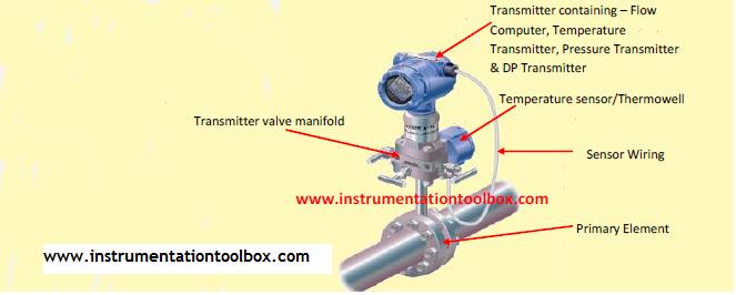
How Multivariable Transmitters Work

A multivariable transmitter is a differential pressure transmitter that is capable of measuring a number of independent process variables, including differential pressure, static pressure, and temperature. When used as a mass flow transmitter, these independent values can be used to compensate for changes in density, viscosity and other flow parameters. A typical multivariable transmitter installation and setup for flow measurement is shown below:
Multivariable Transmitter Installation & SetUp
A Multivariable transmitter delivers unprecedented performance and capabilities by providing three separate


How Pressure & Temperature Changes Affects Flow Meter Accuracy in Gas Flow Measurements

In gas flow measurement, the density of the gas changes as pressure and temperature change. This change in density can affect the accuracy of the measured flow rate if it is uncompensated. There are two exceptions however where uncompensated density change will not affect the flow measurement:
(1) A direct mass flow measurement made with a mass meter – coriolis or thermal mass.
(2) An actual volumetric flow measurement made by velocity type meters – Vortex, Turbine, Ultrasonic, Positive Displacement etc.

The accuracy of all other types of flow measurements are affected by changes in gas density.


Effect of Rangeability & Maximum Flow Rate on Accuracy of DP Flow meters

If you use DP flow meters then you must read this article. It is often believed that DP flow meters have low rangeability typically 3:1. However, with continuous improvement in measurement technology especially pressure transmitters, this assertion is now a myth rather than reality. For DP flow meters, low rangeability means large errors at low flow rates since flow is proportional to square root of differential pressure. Rangeability and maximum flow rates are critical factors that should be well understood before you can accurately specify a DP flow meter or any flow meter for that matter. Having a good understanding of the two concepts can help improve accuracy and increase rangeability of a meter in a given application.
To have a thorough understanding of the effect of rangeability and maximum flow rate has on the accuracy of a DP flow meter, we need to understand the following terms;
(1) Rangeability
(2) Maximum flow
(3) Percent of flow range


Basics of Permanent Pressure loss in Differential Pressure Flow Meters

The standard primary flow sensors commonly used in differential pressure flow meters are the orifice plates, flow nozzles and venturi tubes. These flow meters are often called "head loss" meters because there is a permanent pressure loss downstream these meters. In other words, upstream pressure never recovers to its original value downstream these meters. Various designs of these flow sensors are available which can provide the optimal meter for the desired operating conditions and requirements of the user. A critical factor in choosing a differential pressure flow meter is the pressure loss of the flow sensor. As a rule, when applying differential pressure devices, pressure loss must be small. This is because pressure loss means energy loss and higher pumping/compression costs.

The different installation versions of the primary flow sensors (orifice plates, flow nozzles, venturis) of differential pressure flow meters commonly used in flow measurement are tabulated below:


SelectIion Chart for Point Level Measurement Technologies

Point level measurement is commonly done using the following technologies
(a) Capacitance sensors
(b) Nuclear sensors
(c) Vibrating fork sensors and
(d) Float switches
The above technologies are often best suited to certain process conditions or a combination of process conditions. To apply these technologies, some questions commonly asked include:
  1. Which level measurement technology best suits density changes in the process?

  2. Which technology will suffice for a changing dielectric strength of process fluid?

  3. Which technology can be best used where you have solids, dust, foam, slurries, emulsion, internal obstructions, vapors, viscous/sticky product?

  4. Which technology is best suited for high process temperature limits, high vessel pressure limits, low process temperature limits, low vessel pressure limits?

  5. Which level measurement technology can best resist noise (EMI, motors), product coating etc?

  6. Which technology is best suited a process where there is aeration, agitation, ambient temperature changes, or corrosion?

The above questions are


Basics of Electrical Power Principles in AC Motors – Formulas and Conversion Factors

The Electric power in single phase or three phase AC motors can be seen in two ways:
(a) Electrical power consumed by the AC motors
(b) Mechanical power output often referred to as Shaft power, delivered by the motor

When electrical power is fed into an electric motor using alternating current, a magnetic field is created in the stator which in turn induces voltage in the rotor creating mechanical rotational motion. The rotational mechanical power produced called shaft power is what is used to drive loads like pumps. Below is a schematic showing the relationship between electrical input power (P1) and mechanical or shaft power (P2):


How to Read Electric Motor Nameplate Data

The nameplate of a motor provides important information necessary for proper ordering, replacement and application. To help in the proper application of electric motors, the National Electrical Manufacturers Association (NEMA) and other bodies like the IEC (International Electrotechnical commission) define some basic design, performance and mounting parameters to aid in standardizing electric motors. These parameters are then coded onto the motor nameplate to give a basic definition of what you have received.
Motor nameplate data can be categorized according to the following parameters:

(a) General Data
(b) Electrical input
(c) Mechanical output
(d) Motor Design
(e) Performance
(f) Safety
(g) Reliability
(h) Construction

Nameplate data is the critical first step in determining motor replacement.  It is a treasury of important information about a motor. If you specify, buy, maintain, or replace motors, you should know how to read them by going through this post.
The following parameters are the minimum information that can be found on the nameplates of single and poly-phase induction motors:

General Data
A typical nameplate also include general information such as the motor's brand name, a "Serial No." or other identifying number unique to that motor, that would let the manufacturer trace the motor back through manufacturing. The nameplate also includes the manufacturer's name, and its principal city and state and "Made in U.k." if U.k -made.


Flow Meter Selection Chart

Fluid flow rate is an important measurement in the process industries. Selecting an appropriate flow measurement technique can be a daunting task. Flow metering technologies tend to fall into four classifications: velocity, inferential, positive displacement, and mass. Among the common flow meters used to measure flow include:
(a) Mass flow meters
(b) Magnetic flow meters
(c) Positive Displacement flow meters
(d) Turbine flow meters
(e) Differential pressure flow meters
(f) Ultrasonic flow meters
(g) Swirl and Vortex flow meters
To aid in the selection of


How to Specify a Thermowell

Thermowells are available for light duty applications, high pressures, high temperatures and high velocity applications. They are used to meet many general service industry needs and are selected on the basis of pressure, temperature, flow, vibration and corrosion parameters. The basic thermowell types include: threaded, socket weld, weld in, flanged, sanitary and van stone. The threaded type is generally the least costly and most versatile. The schematic of a typical thermowell and all parts required to specify a thermowell for proper selection is shown below:


How to Size a Control Valve for Liquid and Gas Applications Using a Selection Chart

Control valve sizing is big business. Often there is a thin line between getting it right or wrong with unintended consequences for the process where the control valve is applied. Typically these days, most control valve sizing is done via software supplied by valve manufacturers. However, here the sizing chart presented is a guide for quickly selecting the type of valve required for general-purpose applications before getting down to the nitty-gritty of using a sizing software.  As you examine this selection chart, please be reminded that there are so many special circumstances applicable to many control valve applications that the guide provided here be considered as a very approximate first level guide only.
Before using this chart, make sure you understand the terms, P1, P2 and T1 as defined in the schematic for a control valve in a process shown below:


How to Specify an Orifice Plate

Orifice plates are commonly used in flow measurement applications. After prolonged use, there may be need to order a new orifice plate to replace the one in service. In most industrial applications for large flow measurement, the orifice plate is often contained in a dual orifice chamber fitting and is usually replaced online in these types of fittings. In flange types, the orifice plate is sandwiched between flanges. The main reason for replacing an orifice plate is often due to deterioration and corrosion in service. Therefore to order a new orifice plate, the following specification checklist tabulated below should be handy so that mistakes are not made in the ordering process:


Thermocouple Concepts: Cold Junction Compensation(CJC); Thermocouple Loop Resistance; Thermocouple Degradation

Thermocouple Cold Junction
A thermocouple has two junctions. The difference in temperature of these junctions is what is used to measure temperature. One is called the hot junction which is inserted in the process whose temperature is required to be measured while the cold junction also known as the reference junction is the termination point outside of the process where the temperature is known and where the voltage is being measured. Typically the cold junction is located in a transmitter or signal conditioner.

Thermocouple Cold Junction Compensation (CJC):
The voltage measured at the cold junction correlates to the temperature difference between the hot and cold junctions; therefore, the temperature at the cold junction must be known for the hot junction temperature to be accurately determined. This process is known as cold junction compensation.


You May Also Like: